XG-P25X
20
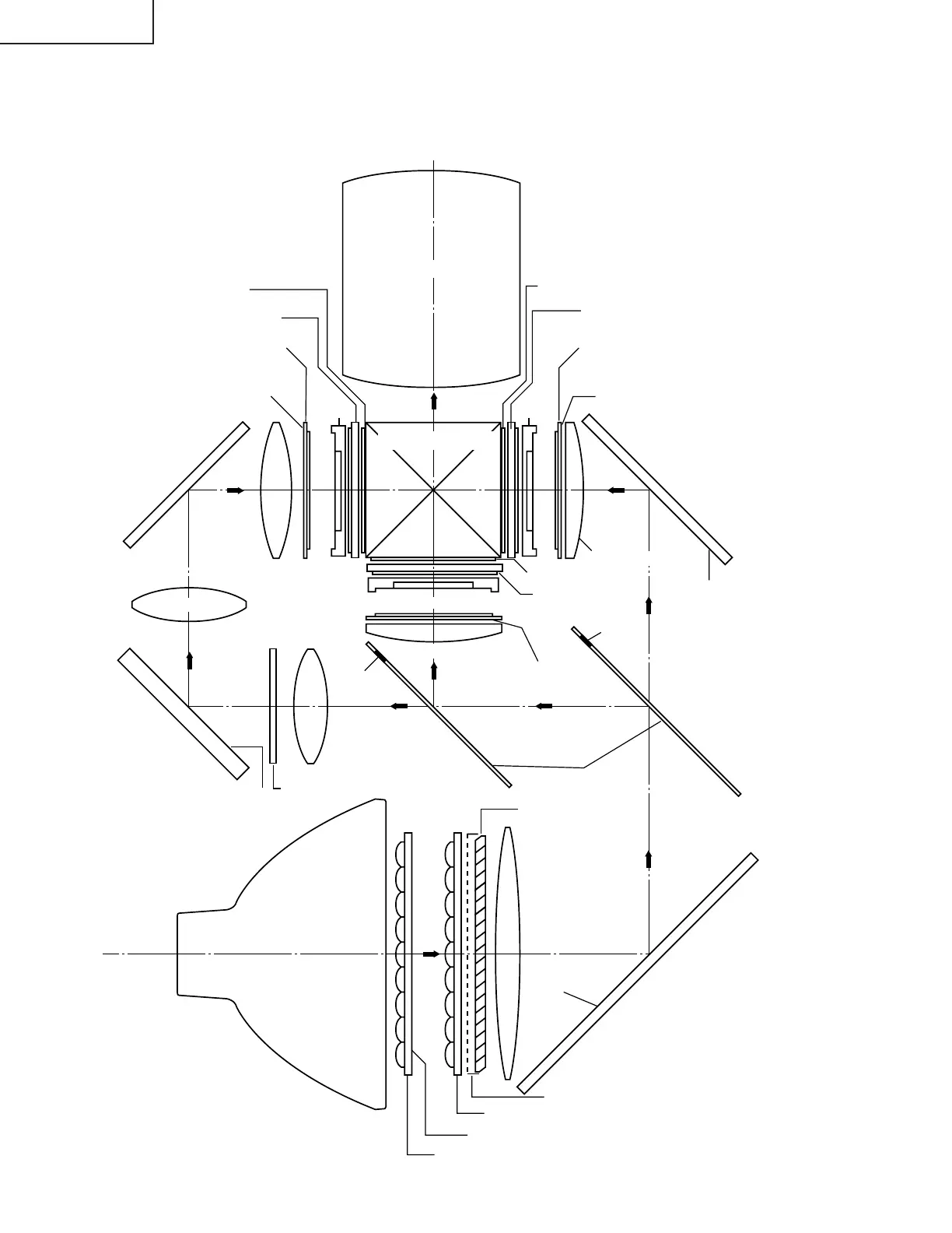
THE OPTICAL UNIT OUTLINE
B-LCD
G-LCD
GREEN
BLUE
BLUE
RED
R-LCD
Dichroic coating
(B transmission)
Incident polarizing plate R
Dichroic coating
(R transmission)
AL-coated mirror R
AL-deposited face
(R reflection)
Marking
Dichroic coating
(R, G transmission)
Marking
G reflector
Dichroic coating
B/G reflector
AL-coated mirror W
AL-deposited
face
Fly-eye lens (outgoing light)
Fly-eye lens (incoming light)
UV-IR coating
UHP lamp
(Light source)
Relay lens 1
UV-absorption-filter
AL-deposited face
AL-coated mirror B
Projection Lens
AL-coated mirror B
Cross dichroic prism
Incident polarizing plate B
Relay lens 1
Relay lens 2
Incident polarizing plate G
Condenser lens G
PBS aperture
Condenser lens R
* M3
M6
G03 L2
G02 L2
G01
M4
M2
M5
M1
PBS(polarization
beam splitter)
L1
1/2λ plate + polarizing plate
1/2λ plate
Sapphire glass
Polarizing plate
1/2λ plate
Sapphire glass
Polarizing plate
Sapphire glass
Polarizing plate
Layout of the optical system
Note: Layout for positioning the optical system.
* The M3 mirrors have a coating
wedge (for different film thick-
ness). Set up these mirrors, with
their markings positioned as
shown above, so that their
coated faces and both sides be
in the correct directions.