XG-P25X
10
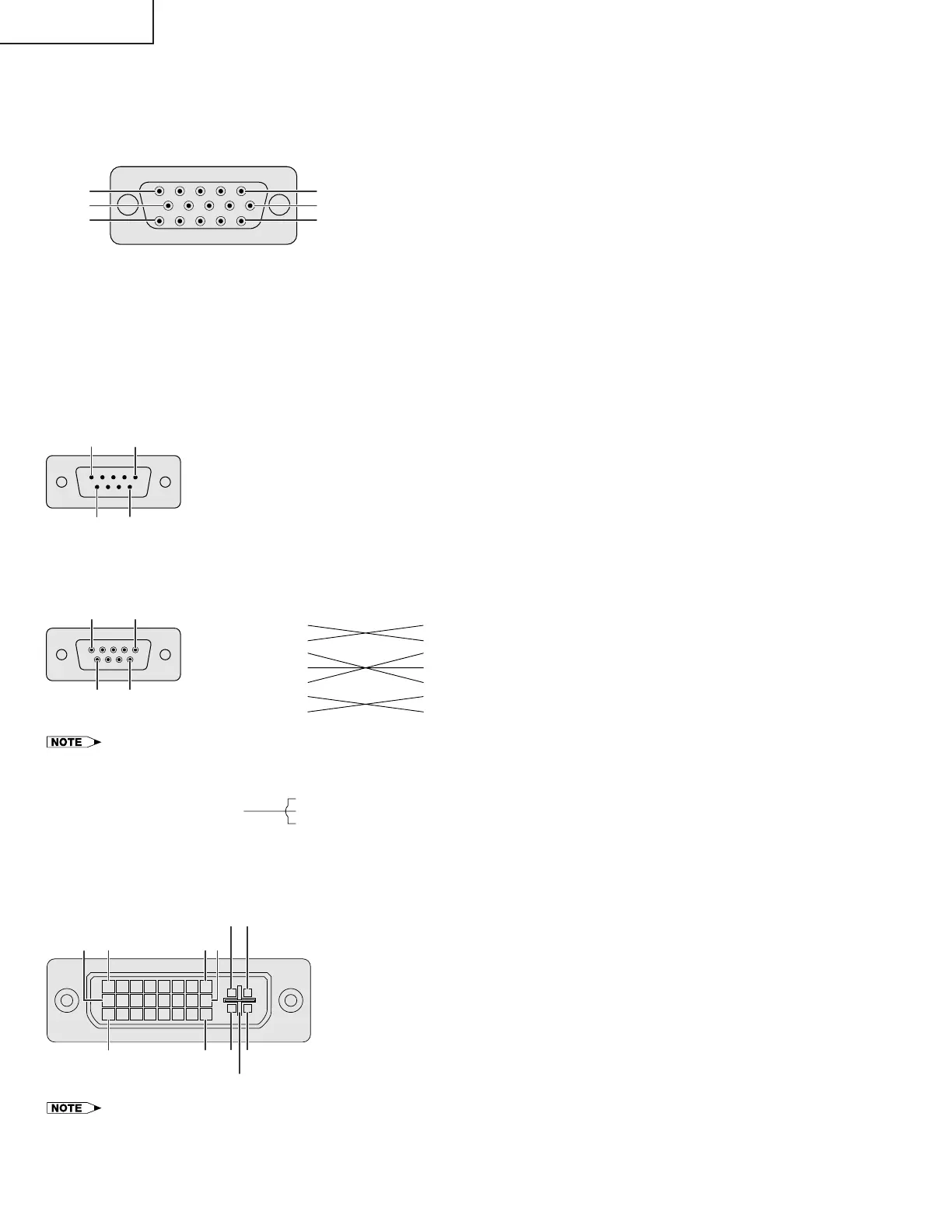
Connection Pin Assignments
RGB Input
Analog
1. Video input (red)
2. Video input
(green/sync on green)
3. Video input (blue)
4. Reserve input 1
5. Composite sync
6. Earth (red)
7. Earth (green/sync on green)
8. Earth (blue)
9. Not connected
10. GND
11. GND
12. Bi-directional data
13. Horizontal sync signal
14. Vertical sync signal
15. Data clock
RS-232C Port: 9-pin D-sub male connector
5
10
15
1
6
11
INPUT 1 RGB and OUTPUT (INPUT 1, 2) Signal Ports: 15-pin Mini D-sub female connector
RS-232C Cable recommended connection: 9-pin D-sub female connector
Pin No. Signal Name I/O Reference
1 CD Not connected
2 RD Receive Data Input Connected to internal circuit
3 SD Send Data Output Connected to internal circuit
4 ER Not connected
5 SG Signal Ground Connected to internal circuit
6 DR Data Set Ready Not connected
7 RS Request to Send Output Connected to internal circuit
8 CS Clear to Send Input Connected to internal circuit
9 CI Not connected
15
69
Signal SignalPin No. Pin No.
• Depending on the system layout, it is necessary to connect Pin 4 and Pin 6 on the controlling device (e.g. PC).
Component Input
Analog
1. P
R
(C
R
)
2. Y
3. P
B
(C
B
)
4. Not connected
5. Not connected
6. Earth (P
R
)
7. Earth (Y)
8. Earth (P
B
)
9. Not connected
10. Not connected
11. Not connected
12. Not connected
13. Not connected
14. Not connected
15. Not connected
INPUT 3 DVI Port: 29-pin
91 816
C1C2
C32417 C4
C5
• *
1
Return for 5 V, Hsync. and Vsync.
• *
2
Analog R, G and B return
• *
3
These pins are not used on this equipment.
Pin No. Name
1 T.M.D.S. Data 2
2 T.M.D.S. Data 2
3 T.M.D.S. Data 2/4 Shield
4 T.M.D.S. Data 4 *
3
5 T.M.D.S. Data 4 *
3
6 DDC Clock
7 DDC Data
8 Analog Vertical Sync
9 T.M.D.S. Data 1
10 T.M.D.S. Data 1
11 T.M.D.S. Data 1/3 Shield
12 T.M.D.S. Data 3 *
3
13 T.M.D.S. Data 3 *
3
14 5 V Power
15 Ground*
1
Pin No. Name
16 Hot Plug Detect
17 T.M.D.S. Data 0
18 T.M.D.S. Data 0
19 T.M.D.S. Data 0/5 Shield
20 T.M.D.S. Data 5 *
3
21 T.M.D.S. Data 5 *
3
22 T.M.D.S. Clock Shield
23 T.M.D.S. Clock
24 T.M.D.S. Clock
C1 Analog Red
C2 Analog Green
C3 Analog Blue
C4 Analog Horizontal sync
C5 Analog Ground*
2
Projector
Pin No.
PC
Pin No.
5
9
1
CD
RD
SD
ER
SG
DR
RS
CS
CI
1
2
3
4
5
6
7
8
9
CD
RD
SD
ER
SG
DR
RS
CS
CI
1
2
3
4
5
6
7
8
9
6
4
5
6
4
5
6