SADP_Operating_ Instructions_0114
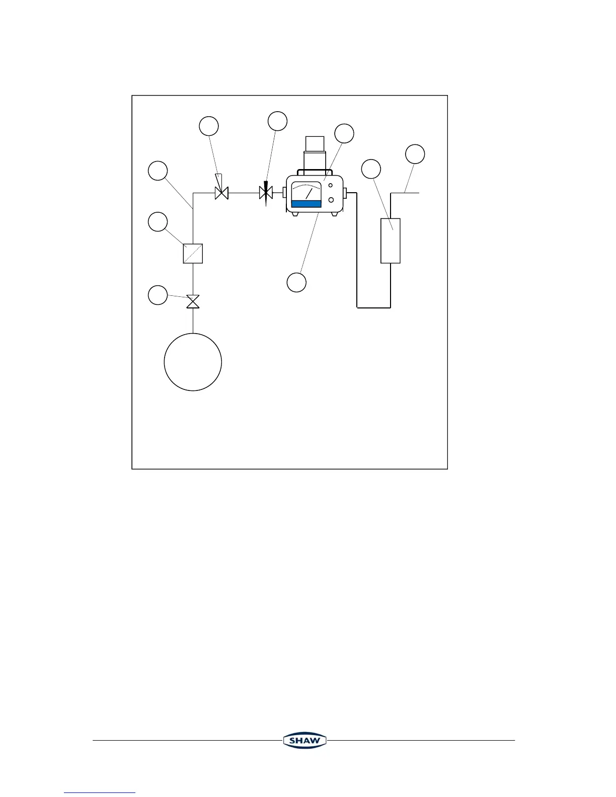
3.2 Piping Installation Schematic
3.3 Piping Schematic Component Index
1. Sample Isolation Valve - This is a recommended item as it allows access to the sample system
without interrupting the main process line.
2. Sample Tube – This should be stainless steel for dry air or gas applications but copper or carbon
steel can be used where wetter gases are to be measured. If any section of the sample tube must
be flexible then PTFE should be used. In most cases, 3mm OD (1/8”) is sufficient as it provides
good system response time with minimum flow. 6mm OD (1/4”) tube can be used where pressure
drops across the 3mm tube are too high
3. Filter Unit – A filter unit is recommended when the samples are likely to contain particulate matter.
If the air/gas sample contains heavy hydrocarbon condensate, the filter must be of the coalescing
type with a drain. The filter unit should be positioned as close to the sample point as practical.
4. Pressure Reduction Valve or Pressure Regulator – the sample is measured at atmospheric
pressure requiring that valve 4 is fitted to the system.
5. Flow Control Valve – This can be a separate item or combined with the flow indicator (8).
6. Sample Connection
7. SADP.
8. Flow Indicator – The recommended sample flow is 5 to 8 L/M.
9. Sample Exhaust – The exhaust is vented to atmosphere or returned to an atmospheric pressure
line.
1
2
3
4
5
6
7
8
Main
Process
Line
Notes
a. The sample point should be on the upper surface of the horizontal pipe, or from a
vertical section of pipe, wherever possible.
b. The sample tube should run upwards from the sample point. If this is not possible,
then an inspection port or drain tap should be installed at the lowest point in the
sample system.
9