Do you have a question about the Sherman digitec DIGIMIG 2OO HIT and is the answer not in the manual?
Details measures to prevent electrical shock during operation.
Advises on preventing poisoning, burns, and noise exposure during welding.
Outlines measures to prevent explosions and fires during welding operations.
Lists technical specifications for the welder unit itself.
Details the adjustable parameter ranges for different welding modes.
Covers duty cycle, IP protection, overheating protection, and MIG gun specs.
Explains how to connect wires for the MMA welding method.
Details the wire connection process for the TIG welding method.
Covers wire connection for MIG and braze welding processes.
Describes connecting wires for welding with self-shielding wire.
Explains wire connection for the optional Spool Gun.
Explains the welding voltage display (A) and its parameters.
Describes the fast wire feed button (C) for wire insertion.
Details the welding current and wire feed speed display (B).
Explains the electrode wire diameter selection button (D).
Describes the source operation control buttons (2T, 4T, SPOT) (E).
Explains the multifunction knob (F) for parameter adjustment.
Describes the welding voltage knob (G) for voltage adjustment.
Details the button (H) for selecting material and shielding gas.
Explains the button (I) for selecting welding methods (MIG, MMA, TIG).
Describes the button (J) for controlling protective gas flow.
Details parameter adjustments for the MMA welding method.
Explains parameter adjustments for the TIG welding method.
Covers parameter adjustments for MIG and synergic MIG modes.
Details the process of preparing aluminum materials for welding.
Guides on the correct storage of welding wire to maintain quality.
Explains how to initiate the arc for the MMA welding method.
Details arc initiation for the TIG welding method.
Guides on initiating the arc for the MIG welding method.
Recommended parameter values for the MMA welding method.
Recommended parameter values for the TIG welding method.
Recommended parameter values for the MIG welding method.
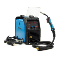
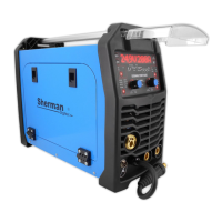
The DIGIMIG 200 HIT synergic welder is a versatile inverter rectifier designed for manual welding of steel and non-ferrous metals. It supports three primary welding methods: MMA (covered electrode), TIG, and MIG/MAG. The MIG/MAG method offers both manual and synergic modes, making it accessible for both experienced welders and hobbyists. The synergic mode simplifies operation by automatically selecting optimal welding parameters based on material type and electrode wire diameter, though users can still make corrections. This flexibility allows for welding with standard wires in a protective gas shield or with self-shielding flux-cored wires by simply changing the polarity.
A notable feature of the DIGIMIG 200 HIT is its compatibility with a Spool Gun (SG) type holder, which includes a mini wire feeder and can accommodate D100 spools of steel or colored wire. This expands its utility for specific welding applications. The device is built using IGBT technology, which contributes to its reduced weight and dimensions while enhancing efficiency and lowering energy consumption. It is designed for use in closed or roofed environments, protected from direct weather conditions.
Before operating the DIGIMIG 200 HIT, it is crucial to read the user manual thoroughly. Start-up and operation should only commence after carefully reviewing the operating instructions. Due to continuous technical development, some functions may differ slightly from the manual's descriptions, which is a result of ongoing improvements, not a device error. Improper handling or unauthorized modifications will void the warranty and are prohibited, as they can compromise safety.
Operators must possess the necessary qualifications for welding, including electric welder qualifications for gas-shielded welding. They must also be familiar with health and safety regulations for electrical power equipment, compressed gas cylinders (argon), and the contents of this manual, ensuring the device is used as intended.
Welding poses several risks, including electric shock, negative effects of the electric arc on eyes and skin, vapor and gas poisoning, burns, explosion and fire hazards, and noise. To prevent electric shock, the device must be connected to a properly protected and grounded electrical installation. All current leads should be installed with the device switched off, and non-insulated parts of the electrode holder, electrode, and workpiece (including the device housing) should not be touched simultaneously. Damaged insulation on holders or leads must be avoided. In high-risk environments like humid conditions or closed tanks, an assistant should be present, and the welder must wear appropriate insulating clothing and gloves. Any irregularities must be reported to competent personnel. Operating the device with covers removed is strictly forbidden.
To protect against the electric arc, operators must wear protective clothing (gloves, apron, leather shoes) and use protective shields or visors with a correctly chosen filter. Non-combustible protective curtains and walls painted in colors that absorb harmful radiation are also recommended.
To prevent poisoning from welding fumes and gases, ventilation devices and extractors should be used in workplaces with limited air exchange. When working in confined spaces (tanks), fresh air should be blown in, and masks or respirators should be worn.
Burn prevention involves wearing appropriate protective clothing and footwear to guard against radiation burns, arc, and spatter. Clothing should be kept free of greases and oils to prevent ignition. Explosion and fire prevention measures include prohibiting operation or welding in rooms with explosion or fire hazards. Welding stations must be equipped with fire-fighting equipment and located at a safe distance from flammable materials. To mitigate noise, earplugs or other hearing protection should be used, and nearby individuals should be warned of the danger. The device should never be used to thaw frozen pipes.
Before starting the device, check all electrical and mechanical connections. Damaged insulation on handles or power cords can cause electric shock. Ensure proper working conditions, including suitable temperature, humidity, and ventilation, and protect the device from precipitation in outdoor settings. The charger should be placed in an easily accessible location.
Only authorized personnel should perform repairs, adhering to safety conditions for electrical devices. It is forbidden to operate the welder in rooms with explosion or fire hazards. The welding station must have fire extinguishing equipment. After use, the power cord must be disconnected from the mains.
If the device has been stored or transported in freezing conditions, it must be brought to a temperature above freezing before operation.
For MMA welding, connect the welding cables to sockets (2) and (5) on the front plate, ensuring correct polarity for the electrode type (indicated on electrode packaging as DCEN or DCEP). The work clamp must be securely fastened to the workpiece. Plug the device into a 230V 50Hz power socket.
For TIG welding, an additional 200A gas-cooled TIG torch with a shielding gas control valve is required. Connect the torch's current terminal to the negative polarity socket (5) and the gas hose to the reducer on the gas cylinder. Connect the positive pole of the source (2) to the welded material with a tong clamp. Plug the device into a 230V 50Hz power socket.
For MIG and braze welding in shielding gases, connect the torch's current clamp to the MIG torch socket (1). Route the gas line from the reducer to the gas connector (7) on the rear wall of the device. Insert the polarity change plug (3) into the "+" socket (2). Connect the negative pole of the source (5) to the welded material with a clamp. Plug the device into a 230V 50Hz power socket.
For welding with self-shielding steel wire, connect the torch's current clamp to the MIG torch socket (1). Insert the polarity change plug (3) into the "-" socket (5). Connect the positive pole of the source (2) to the welded material with a tong clamp. Plug the device into a 230V 50Hz power socket.
For optional Spool Gun welding, connect the torch's current clamp to the MIG torch socket (1). Insert the polarity change plug (3) into the "+" socket (2). Connect the negative pole of the source (5) to the welded material with a clamp. Plug the device into a 230V 50Hz power socket. Set the switch (13) inside the feeder chamber to the Spool Gun position.
Select the appropriate contact tip and wire guide insert for the MIG gun based on the material to be welded and the electrode wire diameter. For steel welding, use steel contact tips and a steel insert. For aluminum welding, use aluminum welding contact tips and a Teflon insert.
The device has a quick wire feed function. Pressing button (C) rapidly ejects the wire, facilitating quick insertion into the holder.
The front panel features displays for welding voltage (A) and welding current/wire feed speed (B), along with adjustable functions and parameters. During MIG/MAG welding, these displays show voltage, adjustable functions, parameters, and error codes.
Button (C) is the fast wire feed button, used to rapidly advance the electrode wire for quick setup. Button (D) is the electrode wire diameter selection button, active only during MIG/MAG welding, confirmed by a control diode.
Button (E) controls source operation, active during MIG/MAG welding in manual and synergic modes. It allows selection of 2T, 4T, or SPOT modes, indicated by a lit diode.
Knob (F) is a multifunction knob used to adjust welding functions and parameters. In manual MIG/MAG mode, it adjusts wire feed speed. In synergic, MMA, and TIG modes, it adjusts welding current. Pressing the knob transitions to other parameters/functions, indicated by a lit diode. Knob (G) adjusts welding voltage, active only during MIG/MAG welding. In manual mode, it sets welding voltage; in synergic mode, it corrects the voltage selected by the program.
Button (H) selects welded material and shielding gas, active during MIG/MAG welding, confirmed by a control diode. Options include:
Button (I) selects the welding method:
Button (J) is the protective gas button, active only during MIG/MAG welding. Pressing and holding it causes shielding gas to flow; releasing it stops the flow.
For MMA welding, parameters include welding current (25-180A), HotStart (0-10), ArcForce (0-10), and VRD (on/off).
For TIG welding, only the welding current can be adjusted.
For MIG and SYN MIG welding, the device offers synergic and manual modes. Synergic mode simplifies parameter selection for less experienced users, automatically setting current and wire feed speed based on material and wire diameter, with voltage correction possible. Manual mode allows users to set welding voltage and wire feed speed as needed.
Additional active buttons during MIG/MAG welding include "test gas flow" and "fast wire feed." In synergic modes, after setting the welding current with knob (F), the welding voltage can be corrected with knob (G).
Inductance adjustment optimizes arc characteristics based on workpiece thickness, welding method, and conditions. It's useful for thin elements in MIG/MAG welding to prevent burn-through and for braze welding galvanized elements. Changing inductance also reduces spatter in CO2 shielding; higher inductance (+) means less spatter, while negative inductance (-) increases it. Optimal inductance depends on several factors and should be determined experimentally. This parameter also enables braze welding of thin (up to 3 mm) galvanized elements using CuSi3 copper alloy wires in pure argon or Ar/CO2 (82/18) mixtures.
The welder includes synergic programs for various materials, wire diameters, and shielding gases. For carbon steel, options include CO2, MIX (Ar+CO2 82/18), and FLUX (self-shielding wire). For Aluminum (ER 5356), Argon is recommended. High-grade argon (4.8 or above) is recommended.
While synergic mode provides recommended parameters, these apply to typical consumables and shielding gases. When welding different alloy materials, parameters may need adjustment. Synergic mode serves as a starting point for precise adjustments. Manual MIG mode is particularly useful for brazing, allowing precise setting of voltage and wire feed speed. Argon is recommended as shielding gas, but Ar/CO2 mixtures also yield good results. Inductance should be experimentally selected based on weld shape, material thickness, and type. Copper-based binders like CuSi3 or SG-CuAl are commonly used. A handle not longer than 3m with a Teflon insert is recommended.
In synergic mode, a program for aluminum welding (AlMg5 wire type ER 5356) is available for various structures and sections. Aluminum welding requires experience, knowledge, and adherence to specific practices. The synergic program selects output parameters for appropriate materials and wire types, but voltage and inductance corrections may be needed for desired results.
Before welding aluminum, ensure:
Workplace preparation:
Material preparation:
Proper storage of welding wire:
For aluminum alloys, use high-quality pure argon (not less than 4.8). Gas flow should be selected based on thickness and welding speed. Counterclockwise process direction yields good results.
For MMA method:
For TIG method:
For MIG method:
Daily maintenance includes keeping the welder clean and checking external connections, electrical wires, and cables. Replace consumables regularly. Periodically clean the device's interior by blowing it with compressed air to remove dust and metal filings from control boards, wires, and electrical connections. At least every six months, perform a general inspection of electrical connections, focusing on shock protection, insulation, and cooling system operation. Damage resulting from inappropriate use or failure to follow maintenance recommendations is not covered by warranty.
Store the device at -10°C to +40°C and relative humidity up to 80%, free from corrosive fumes and dust. Transport packed devices in covered vehicles, secured against movement, and in their proper position.
The DIGIMIG 200 HIT welder should be operated in an atmosphere free of corrosive components and high dust. Avoid dusty places, areas near grinders, etc. Dust and metallic filings on control boards, wires, and connections can cause electrical shorts and damage. Avoid high humidity, especially where dew forms on metal elements. If a cold device is brought into a warm room and dew forms, wait until it is completely dry and warm before operation. Operating a cold welder in these conditions can cause damage. If used outdoors, place it under a roof to protect it from adverse weather.
The device should operate within these conditions: supply voltage RMS value changes not greater than 10%, ambient temperature from -10°C to +40°C, atmospheric pressure 860 to 1060 hPa, relative humidity not greater than 80%, and height above sea level up to 1000m.
| Welding Method | MIG/MAG, MMA, TIG |
|---|---|
| Input Voltage | 230V |
| Welding Current Range MIG/MAG | 30-200A |
| Wire Diameter | 0.6-1.0 mm |
| Electrode Diameter | 1.6-4.0 mm |
| Protection Class | IP21S |
| Duty Cycle | 60% |