28
Installation/removal
Installing the switch unit
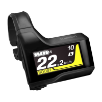
3. Install the cable cap.
When routing the electric wire in the direction of the stem
Install as shown in the figure.
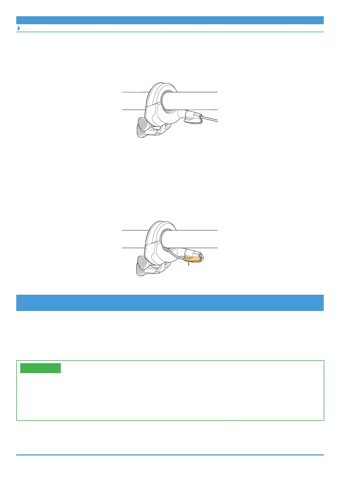
When routing the electric wire internally towards the end of the handlebar
Route the electric wire as shown below.
(1) After installing the cable cap, route the electric wire along the guide on the cable
cap.
(2) Pull the opposite end of the electric wire to draw the excess length of wire into the
handlebar.
Guide
2-switch/3-switch type switch unit
For models: SW-EM800-L, SW-E7000, SW-E6010, SW-E6000
The 2-switch/3-switch type switch unit can be installed to a Ø22.2 handlebar. This section
explains the installation method when wiring from the switch unit along the handlebar on the
outside.
TECH TIPS
• The electric wire may be fixed to the main body, or may be detachable and sold
separately, depending on the model of the switch unit.
• Cord bands may be included or may be sold separately, depending on the model of the
switch unit.
 Loading...