32
Installation/removal
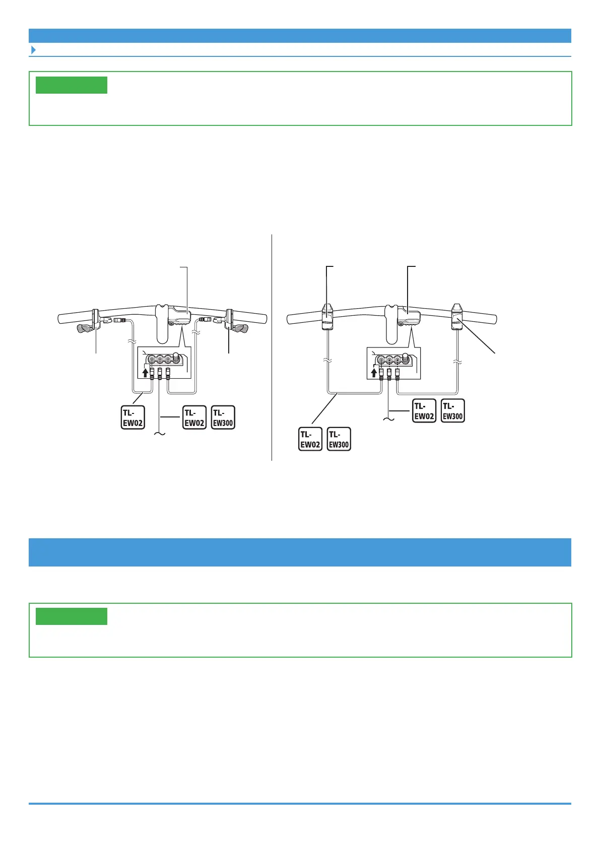
Wiring around the cockpit (clamp band type cycle computer)
TECH TIPS
• Configurations without a switch unit are possible, depending on the cycle computer.
1. Wire around the cockpit.
• Connect the cycle computer and the switch units using the electric wires.
• Switch units and drive units can be connected to any of the E-TUBE ports on the cycle
computer. However, it is recommended to connect as shown in the figure.
Cycle computer
Left switch
Left switch
Right switch Right switch
To drive unit
MTB type switch unit
To drive unit
2-switch/3-switch type switch unit
Cycle computer
2. Prepare to wire to the drive unit.
Refer to the “SHIMANO STEPS Dealer's Manual.”
Example: Routing the electric wire
Use cord bands and a cord clip to organize the wiring around the cockpit.
TECH TIPS
• A cord clip may be included with the cycle computer or may be sold separately.
 Loading...