Page 15
845180 SHOPSMITH MARK V
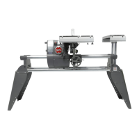
4. Loosen the Quill Feed (shown in Figure
41) and extend the Quill so the Saw
Blade is centered beneath the slot in the
Table Insert. When it is centered, lock the
Quill Feed.
Figure 41
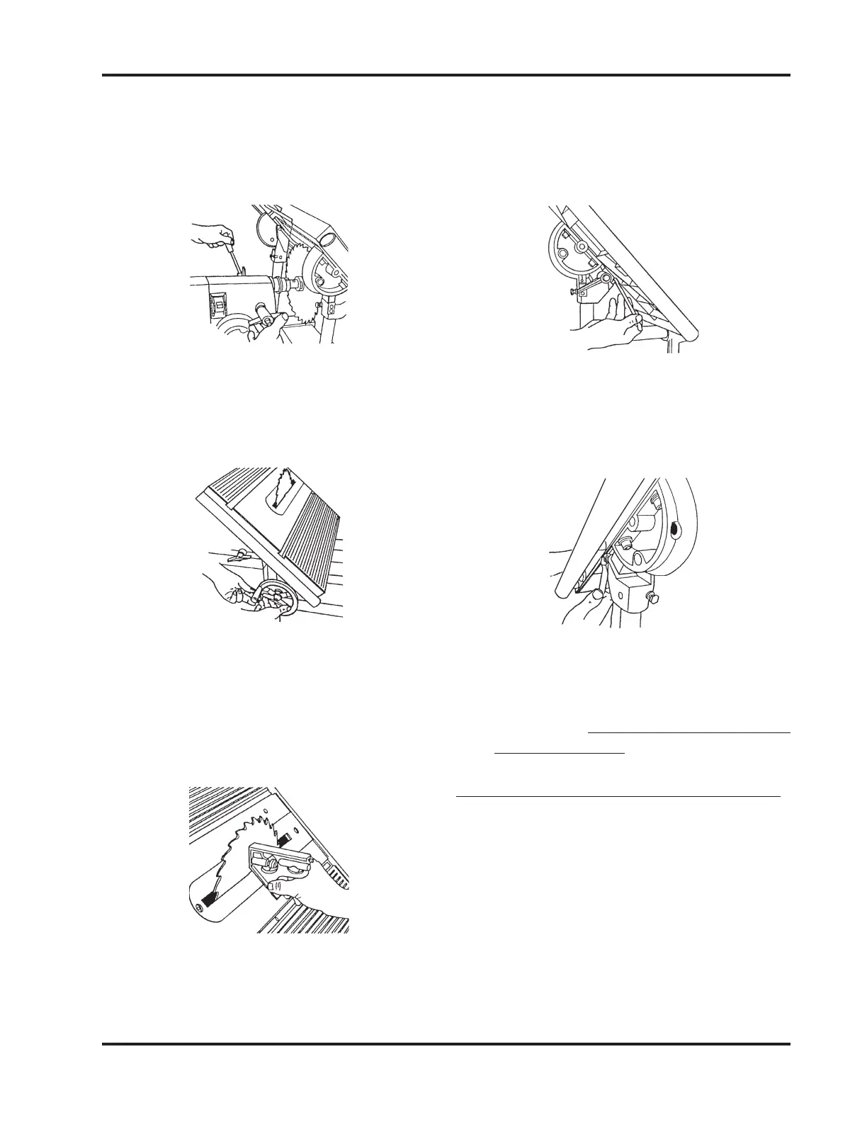
5. Lower the Worktable so the Saw Blade
extends through the slot. See Figure 42
Lock the Table Height.
Figure 42
6. Remove the bar from the Combination
Square and place the square against the
Saw Blade and the Worktable, as shown
in Figure 43. Make sure the Combination
Square doesn't rest on the Table Insert.
Figure 43
7. If the Worktable is not exactly 45° to the
Saw Blade, adjust the Worktable so it is.
8. Tighten the Tilt Lock, then use a 1/2"
Wrench to adjust the 45° Stop on the
front side of the Worktable (shown in
Figure 44).
Figure 44
9. Also, the back side of the Worktable
(shown in Figure 45). The stops should
just contact the underside of the Table.
Figure 45
10. Loosen the Tilt Lock and move the Table.
To recheck the 45° stops, repeat Steps 4
through 8. (It is very important to re-
check the setting!)
ALIGN THE MITER GAUGE SLOTS
1. Return the Worktable to the horizontal
0° stop and tighten the Tilt Lock. The
Carriage Lock and Headstock Lock
should also be tightened.
2. Place the Miter Gauge in the Right Miter
Gauge Slot, and use a 5/32" Allen Wrench
to remove the Quick Clamp from the
Safety Grip, as shown in Figure 46.