SHOPSMITH MARK V 845180
Page 18
slide it back and forth in the Slot to check
if the Miter Gauge scrapes against the
Table. If the Miter Gauge rocks or scrapes
the Table, adjust the Glides.
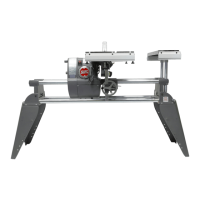
Figure 56
3. If the Glides need to be adjusted, do the
following:
Miter Gauge shown
before adjusting the glides.
a. Remove the Miter Gauge from the
Slot and turn it over.
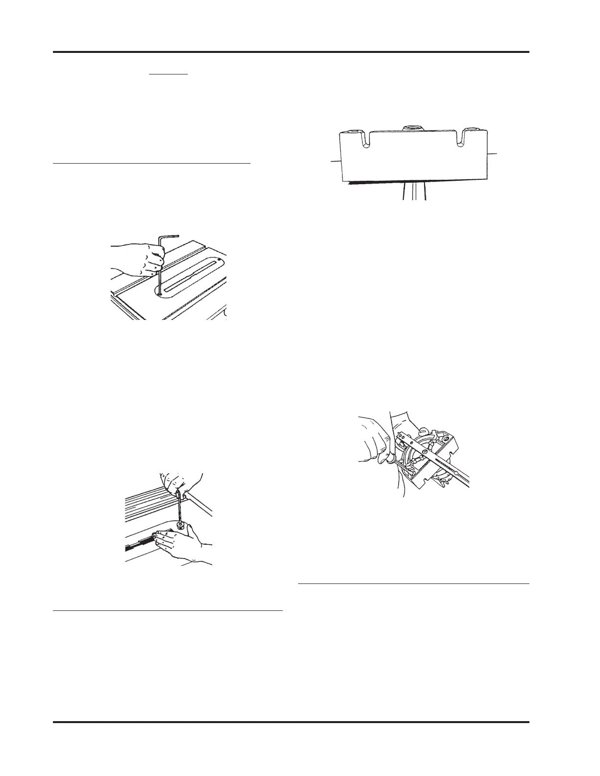
b. Use a Medium Screwdriver to ad-
just the Glides in or out, as illus-
trated in Figure 71, so that the Glides
hold the Miter Gauge 1/64" to 1/
32" off the Worktable and the Miter
Gauge does not rock in the Slots.
Figure 57
4. Return the Miter Gauge to the Slot and
recheck and readjust it, if needed.
ADJUST THE MITER GAUGE FACE
1. Remove the Safety Grip from the Miter
Gauge.
2. Put the Miter Gauge in the Right Slot and
place the Combination Square against
the Saw Blade and Miter Gauge Face, as
seen in Figure 58.
NOTE
Tighten the Bolts only after the Table Tilt Lock is
secured. Otherwise the Worktable will bow or bind
the next time the Table Tilt Lock is tightened.
INSTALL THE TABLE INSERT
1. Place the Table Insert in the Worktable
recess. Use a 5/32" Allen Wrench to start
both screws. See Figure 54.
Figure 54
2. First tighten the rear screw. Then the
front of the insert will be sprung slightly
above the Table. Level the insert by plac-
ing your hand on the front of the insert,
and slowly turning the front screw until
it draws the front of the insert flush with
the Worktable surface. Shown in Figure
55.
Figure 55
ADJUST THE MITER GAUGE GLIDES
1. Place the Miter Gauge in the Worktable's
Miter Gauge Slot.
2. Check to see if the Miter Gauge wobbles
side-to-side, typified by Figure 56. Also,