SHOPSMITH MARK V 845180
Page 22
Figure 72
ALIGN THE RIP FENCE
(MARK V MODEL 510)
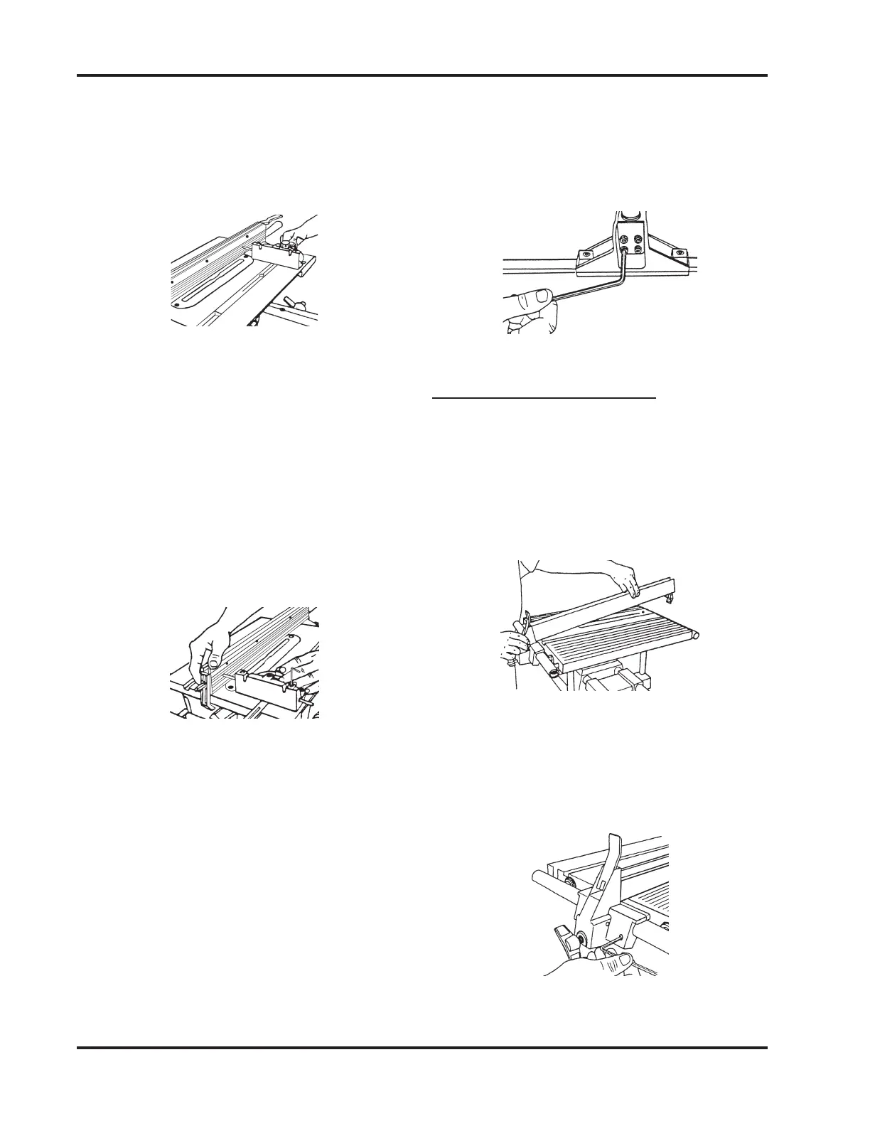
1. Place the Rip Fence on the Worktable by
first putting the Fence Base on the front,
as demonstrated in Figure 73, then low-
ering the rest of the Rip Fence.
Figure 73
2. Use a 5/32" Allen Wrench to back out the
Adjusting Set Screw from the Fence Base
so it doesn't contact the infeed Table
Tube, as shown in Figure 74.
Figure 74
c. Adjust the Fence by pulling or push-
ing it closer to, or farther from, the
5/32" Allen Wrench, as shown in
Figure 71.
d. Lock the Rear Clamp Lever. Again,
slide the Miter Gauge from front to
back, as described in Step 11. The
Fence should be parallel with the
Miter Gauge Slot. If not, repeat Steps
10 through 12b.
4. Slide the Miter Gauge back and forth in
the Slot, as seen in Figure 70. The tip of
the Allen Wrench should keep in slight
contact with the Rip Fence. Watch that
you don't scratch the Fence.
Figure 70
5. If it pulls away from or binds against the
Rip Fence, the Fence needs aligning. To
align the Rip Fence, do the following:
a. Loosen the Rear Clamp Lever.
b. Loosen the four Socket Head Cap
Screws under the infeed end cast-
ing just enough to move it with firm
pressure.
Figure 71
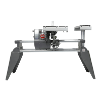
e. Once aligned, tighten the Socket
Screws with a 5/32" Allen Wrench,
as shown in Figure 72. Repeat Step
12c to double check alignment. (It is
very important to recheck the align-
ment!)