Page 7
845180 SHOPSMITH MARK V
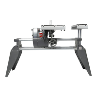
Figure 3
WARNING
Always make sure the MARK V Head-
stock and Carriage are locked and all
Casters are raised off the floor before
lifting the MARK V into the vertical
Drill Press position.
3. Use your fingers to tighten the Base Lock.
NOTE
The Base Lock is slightly off center to the counter-
sink found in the Base, as shown in Figure 4. This
offset allows the Base Lock to more firmly hold the
Base Arm in place.
Figure 4
4. Move the Worktable into the 90° posi-
tion by loosening the Table Tilt Lock,
then putting the Worktable in the hori-
zontal 90° position, as shown in Figure 5.
Retighten the Table Tilt Lock only enough
to allow movement with firm pressure.
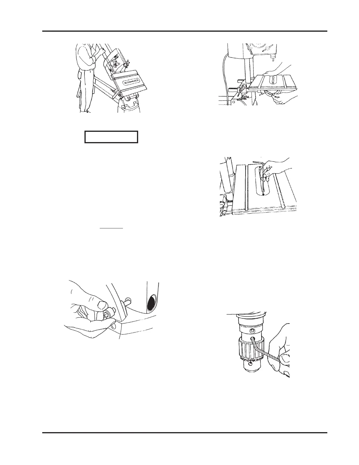
Figure 5
5. Use a 5/32" Allen Wrench to remove the
Table Insert, as demonstrated in Figure
6.
Figure 6
6. To install the Drill Chuck, mount the
Chuck on the Spindle and align the
Chuck's Set Screw with the Spindle
Knob's Set Screw, as shown in Figure 7.
This allows the Chuck's Set Screw to set
on the flat part of the Spindle. Use a
5/32" Allen Wrench to securely tighten
the Drill Chuck's Set Screw.
Figure 7
7. Install a 1/2" Straight Drill Bit in the
Drill Chuck and use the Chuck Key to
lock it place. See Figure 8.