ENGLISH
ENGLISH
5
2
3
4
5
6
7
8
10
11
12
1
Á
Á
Á
Á
Á
Á ÁÁÁÁÁÁÁ
ÁÁÁÁÁ
ÁÁ
ÁÁÁÁÁÁÁ
Á
Á
Á
Á
Á
ÁÁ
ÁÁ
Á
Á
Á
Á
ÁÁ
ÁÁ
Á
Á
ÁÁ
ÁÁ
Á
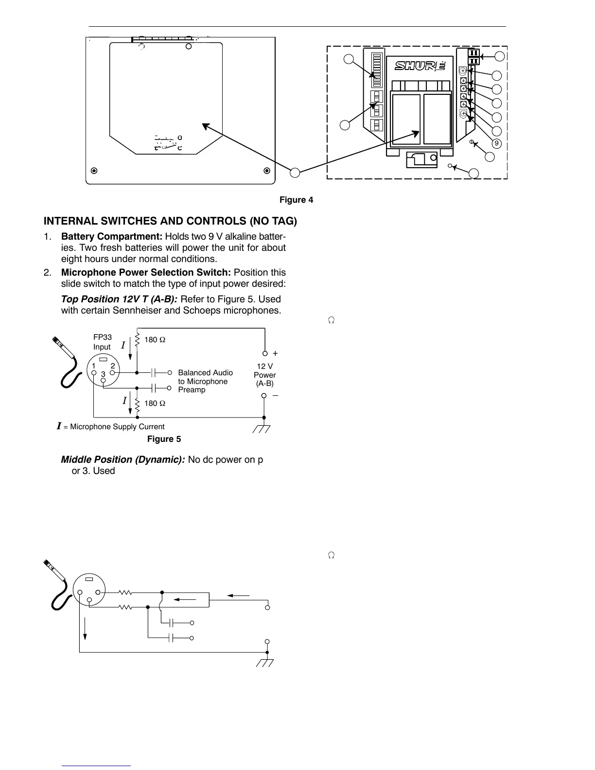
Figure 4
9
INTERNAL SWITCHES AND CONTROLS (NO TAG)
1. Battery Compartment: Holds two 9 V alkaline batter-
ies. Two fresh batteries will power the unit for about
eight hours under normal conditions.
2. Microphone Power Selection Switch: Position this
slide switch to match the type of input power desired:
Top Position 12V T (A-B): Refer to Figure 5. Used
with certain Sennheiser and Schoeps microphones.
12
+
–
Balanced Audio
to Microphone
Preamp
Figure 5
FP33
Input
I
3
180 Ω
180 Ω
12 V
Power
(A-B)
I = Microphone Supply Current
I
Middle Position (Dynamic): No dc power on pins 1,
2, or 3. Used with dynamic microphones or condenser
microphones that have internal batteries.
Bottom Position (Phantom): Refer to Figure 6. In-
ternal DIP switch 11 selects 12 volts or 48 volts. 48 V
phantom power drains the batteries faster than 12 V
phantom power. Used with all condenser micro-
phones that do not require T power.
–
12–48 V
Phantom
Power
Balanced Audio
to Microphone
Preamp
Figure 6
Phantom
FP33 Input
I = Microphone Supply Current
I
I
R
R
1
2
3
Phantom
+
–
R = 680 Ω for 12 V
R = 6.8 kΩ for 48 V
I
Caution: Balanced dynamic microphones will not be
damaged by phantom power but may be damaged by
T power.
3. Fuse and Spare Fuse: Designed to protect the FP33
from damage that may result from using a common ex-
ternal dc power supply with other electronic devices.
Caution: Damage may result when using a common
external dc power supply with other electronic devices
that are “positive ground.” Separate power supplies are
recommended.
4. Level R Potentiometer: Attenuates the level of the
FP33 right channel program audio that is fed to the
headphone/monitor circuit. This does not affect the
Monitor In levels at the headphone output.
5. Peak LED R Potentiometer: Adjusts the Right Peak
LED to light at a preset output level. The factory setting
is +17 dBm. The user adjustment range is 0 dBm to
+17 dBm. See the Peak LED Adjustment paragraph.
6. Peak LED L Potentiometer: Adjusts the Left Peak
LED to light at a preset output level. The factory setting
is +17 dBm. The user adjustment range is 0 dBm to
+17 dBm. See the Peak LED Adjustment paragraph.
7. Lim Adj R Potentiometer: Adjusts the Right limiter to
operate at a preset output level. The factory setting is
+15 dBm. The user adjustment range is 0 to +15 dBm.
See the Limiter Threshold Adjustment paragraph.
8. Lim Adj L Potentiometer: Adjusts the Left limiter to op-
erate at a preset output level. The factory setting is
+15 dBm. The user adjustment range is 0 to +15 dBm.
See the Limiter Threshold Adjustment paragraph.
9. Level L Potentiometer: Attenuates the level of the
FP33 left channel program audio that is fed to the head-
phone/monitor circuit. This does not affect the Monitor
In levels at the headphone output.
10. Meter Adj R Potentiometer: Adjusts the Right meter to
indicate 0 VU at a preset output level. The factory setting
is +4 dBm. The user adjustment range is 0 to +16 dBm.
Refer to the VU Meter Adjustment paragraph.
11. Meter Adj L Potentiometer: Adjusts the Left meter to
indicate 0 VU at a preset output level. The factory set-
ting is +4 dBm. The user adjustment range is 0 dBm to
+16 dBm. See the VU Meter Adjustment paragraph.
12. Internal DIP Switches: 12 internal DIP switches al-
low the user to customize operation. The function of
each DIP switch is listed in the table on the following
page.