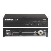
Shure LX4 Diversity Receiver
22
Bench Checks
25D1008 (BK)
n If the THD drops to an acceptable level, check the local oscillator
frequency. Also, check FL100, FL101, FL200, and FL201 for
polarity.
n If the audio circuitry works correctly but the audio LEDs fail to
light when the standard test signal is applied, or remain on when
there is no modulation, check dc voltages at U11, and U4A.
n Check the audio LEDs. Replace any defective components.
Rf Problems
n Make sure that the rf test signal is being input to the correct
diversity channel. If there is no deflection on the oscilloscope at
TPA4 (TPB4) when the rf coils are adjusted, check the operation
of the local oscillator.
n Turn off the rf generator and measure the injection level at TPA3
(TPB3) with a spectrum analyzer and FET probe. It should be
approximately –15 to –20 dBm.
n If the level is correct, check the frequency of the local oscillator
signal with the frequency counter. It should be 10.7 MHz below
the operating frequency of the receiver, with a tolerance of ± .015
MHz. For example, to receive 169.445 MHz, the local oscillator
frequency would be 158.745 MHz, ± .015 MHz.
n Crystal Y100 operates at one-third of this frequency, or 52.915
MHz. The nominal crystal frequency, which is stamped on the
part, is 3.333 kHz lower, or 52.911667 MHz in this example.
This is because the load reactance of the oscillator is not
precisely zero.
n If any of the rf coils will not tune properly, see if the associated
frequency-dependent capacitor(s) are missing or of the wrong
value. If the IF coil will not tune, check C130 (C230).
n If all of the coils tune, but the rf signal level is low, check dc
voltages and components at rf amplifier Q100 (Q200).
n If everything is working correctly, the dc voltage at TPA4 (TPB4)
will be between 1.0 and 2.0 Vdc with a –95 dBm rf input signal,
depending on component parameters and receiver frequency.
Muting
n With TPA7 (TPB7) connected to ground, the appropriate diversity
channel should be squelched and the diversity A (B) LED should
be off, regardless of the presence or absence of an rf input sig-
nal in that channel. If not, check dc voltages at U3, U1, U6, and
U2. Investigate any irregularities. Replace any components that
are found to be defective.
n If the squelch circuit works but has insufficient adjustment range,
check for low voltage at TPA4 (TPB4) with a –100 dBm rf input
signal.
n Low rf levels at the input of U100 (U200) will cause inadequate
noise at the output of U1C (U2C). In order for the noise squelch
circuits to function, the detector portions of U100 (U200) must
also be functioning correctly.
n Also check the dc voltages and component values of noise am-
plifiers U1B (U2B) and high-pass filters U1C (U2C), if necessary.

 Loading...