Shure LX4 Diversity Receiver
Preliminary Tests925D1008 (BK)
Audio Tests
RF SIGNAL GENERATOR
NOTE: DC VOLTAGES ARE PRESENT AT MOST
RF TEST POINTS. USE A DC BLOCK ON THE
RF SIGNAL GENERATOR TO PROTECT
TEST EQUIPMENT.
AUDIO ANALYZER
12.5 – 18.9 VDC
ANTANT
OUTPUTS
HI Z
BAL
MIC LINE
POWER
AB
DC BLOCK
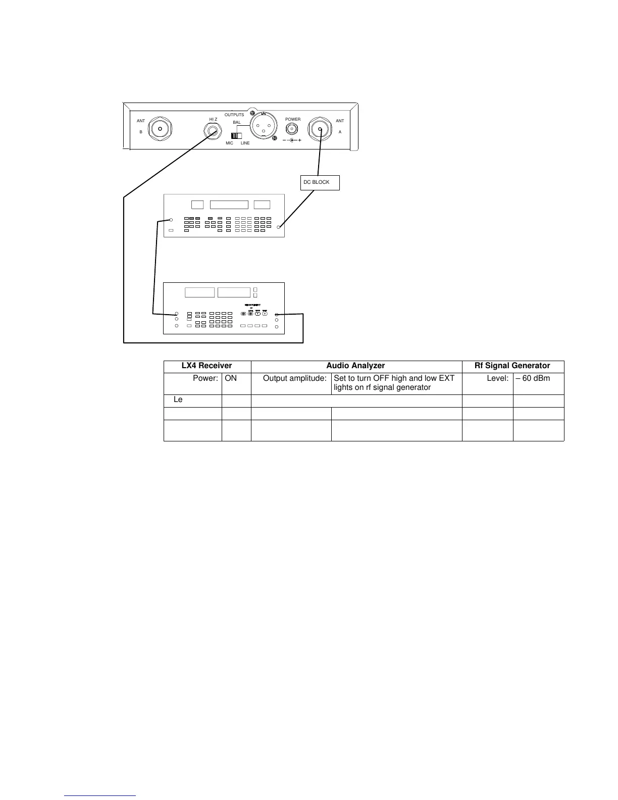
LX4 Receiver Audio Analyzer Rf Signal Generator
Power: ON Output amplitude: Set to turn OFF high and low EXT
lights on rf signal generator
Level: – 60 dBm
Level (gain): Max Filters: Deviation: 15 kHz
Squelch: Mid 400 Hz High-Pass: ON Modulation: EXT 1 kHz
30 kHz Low-Pass: ON Frequency: receiver
frequency
Figure 3. Audio Test Set-Up, steps 1 – 5
Note: The amplitude may have to be adjusted so that neither the HI EXT
nor the LO EXT LEDs on the rf signal generator are on. This amplitude
should be between 1.4 and 1.5 V rms.
1. Set the rf signal generator level to –60 dBm, its deviation to
15 kHz, and its external modulation to 1 kHz.
2. Adjust the audio analyzer’s output amplitude so that the high and
low EXT lights on the rf signal generator are off.
3. Using a 3.3 kΩ load, connect the receiver’s unbalanced audio
output to the audio analyzer. The receiver’s volume control
should still be in its maximum position.
4. Engage the 400 Hz high-pass filter and the 30 kHz low-pass filter
on the audio analyzer.
5. Verify the following receiver measurements:
S Audio level is 400 mVrms, "90 mV. Record the
measurement as a reference level for the following steps.
S total harmonic distortion (THD) is <0.75%.
 Loading...


