Shure LX4 Diversity Receiver
10
Preliminary Tests
25D1008 (BK)
RF SIGNAL GENERATOR
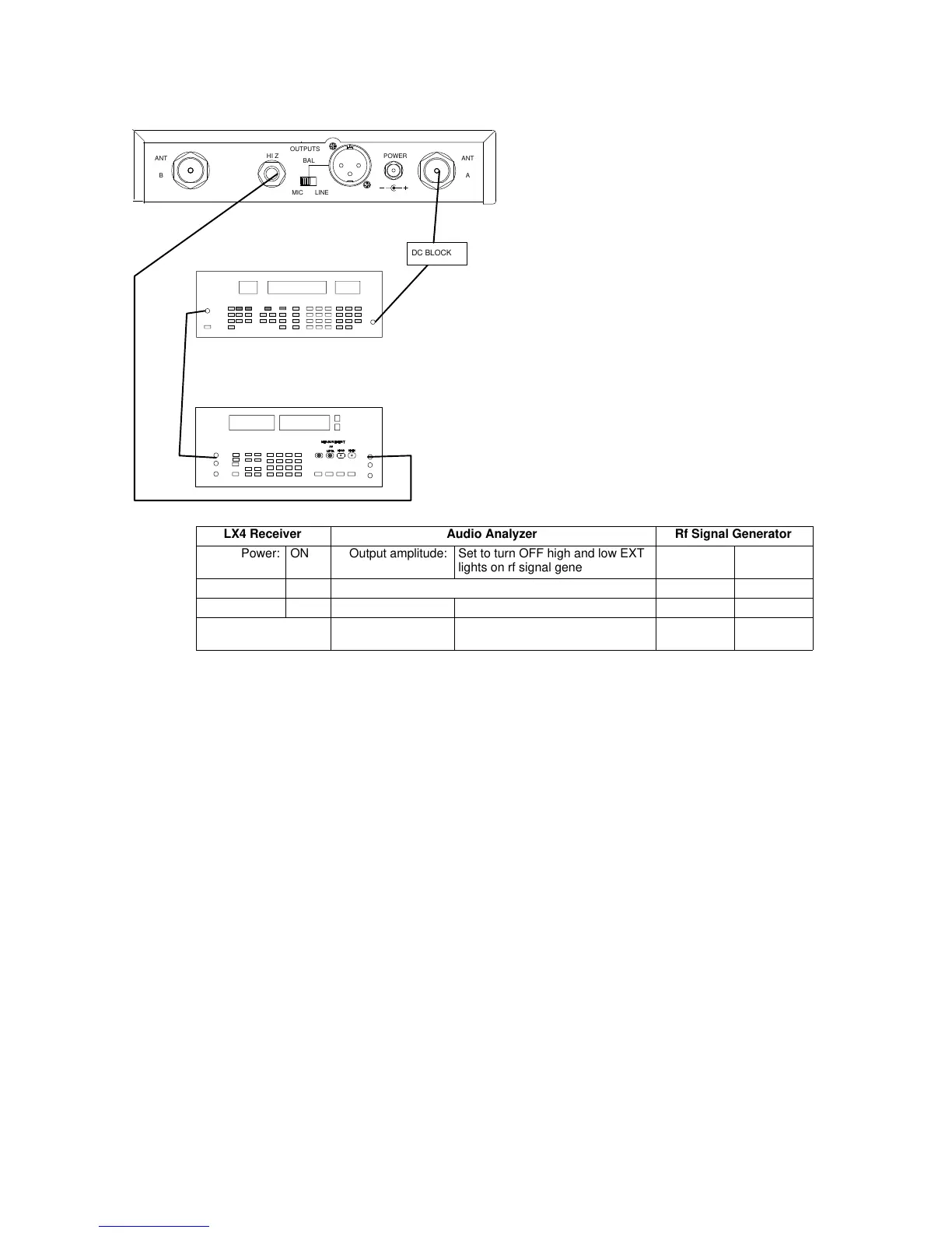
NOTE: DC VOLTAGES ARE PRESENT AT MOST
RF TEST POINTS. USE A DC BLOCK ON THE
RF SIGNAL GENERATOR TO PROTECT
TEST EQUIPMENT.
AUDIO ANALYZER
12.5 – 18.9 VDC
ANTANT
OUTPUTS
HI Z
BAL
MIC LINE
POWER
AB
DC BLOCK
LX4 Receiver Audio Analyzer Rf Signal Generator
Power: ON Output amplitude: Set to turn OFF high and low EXT
lights on rf signal generator
Level: – 60 dBm
Gain: Max Filters: Deviation: 15 kHz
Squelch: Mid 400 Hz High-Pass: OFF Modulation: EXT 1 kHz
30 kHz Low-Pass: ON Frequency: Receiver
frequency
Figure 4. Audio Functional Test Set-Up, steps 6 – 14
6. Use external modulation only on the rf signal generator. Input a
100 Hz signal from the audio analyzer to the external modulation
input of the rf signal generator.
7. Disengage the 400 Hz high–pass filter on the audio analyzer.
8. Verify that the receiver’s unbalanced audio output is within
+2 dB, –1 dB of the reference level recorded in step 5.
9. Change the audio analyzer’s frequency to 10 kHz.
10. Verify that the receiver’s unbalanced audio output is –7.5 dB to
–10.5 dB from the reference level recorded in step 5.
11. Place a 150 Ω load across the receiver’s balanced output. Verify
that it is in the MIC position.
12. Connect this output to the audio analyzer and select the float
position. Verify that the output is 65 mVrms, "15 mV.
13. Remove the 150 Ω load.
14. Take the audio analyzer input out of the float position.
Repeat this test for channel B.
After all testing has been completed, remove the test cable and reinstall
the antenna. If the receiver passes these tests, the unit is functioning
correctly and does not require alignment.
 Loading...


