Shure Incorporated
7/14
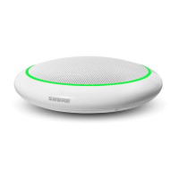
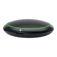
In this configuration, the LED color reflects the microphone state, as controlled by the user with the PUSH button.
Green: microphone active
Red: microphone muted
Button Configuration
For local mute control operation, use DIP Switches 1 and 2 to configure the button behavior.
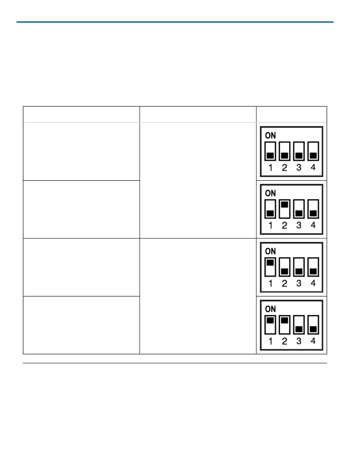
Button Behavior SWITCH OUT Logic Signal DIP Switch Setting
Momentary: push-to-mute (as shipped). When pushed, SWITCH OUT (red wire)
falls to 0 V. When released, SWITCH
OUT returns to +5 V.
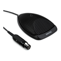
Momentary: push-to-talk
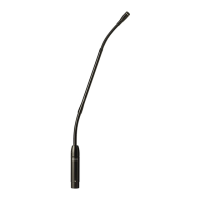
Toggle: Push and release to toggle the
microphone on or off. Mic is active when
powered on.
Push and release sets SWITCH OUT to
0 V. Push again to toggle back to +5 V.
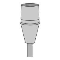
Toggle: Push and release to toggle the
microphone on or off. Mic is mute when
powered on
Logic Mute Control (Automatic Mixing)
Set DIP Switch 3 up to configure the microphone for logic control applications where audio from the microphone
is muted by an external device, such as an automatic mixer. In this mode, the local mute function of the PUSH but-
ton is bypassed (the microphone always sends audio) and the LED does not respond directly from pushing the
button.