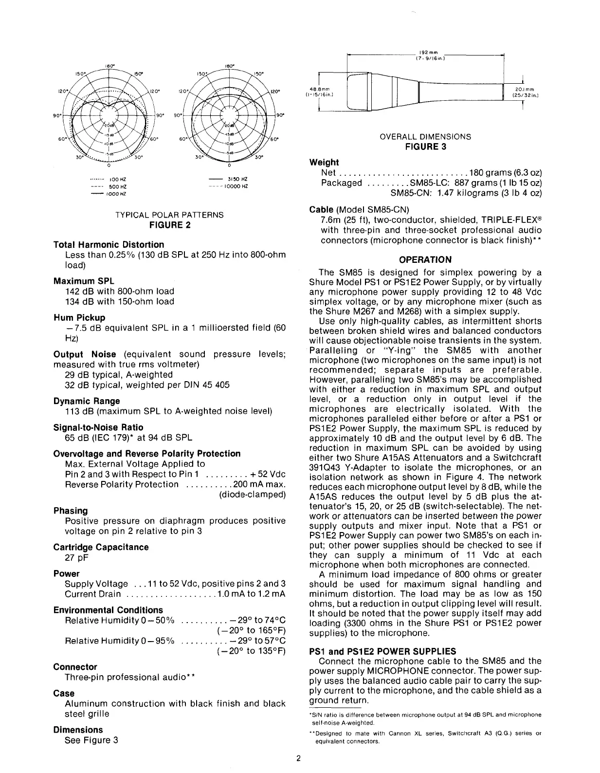
TYPICAL POLAR PATTERNS
FIGURE 2
Total Harmonic Distortion
Less than 0.25% (130 dB SPL at 250 Hz into 800-ohm
load)
Maximum SPL
142 dB with 800-ohm load
134 dB with 150-ohm load
Hum Pickup
-7.5 dB equivalent SPL in a 1 millioersted field (60
Hz)
Output Noise
(equivalent sound pressure levels;
measured with true
rms voltmeter)
29 dB typical, A-weighted
32 dB typical, weighted per DIN 45 405
Dynamic Range
113 dB (maximum SPL to A-weighted noise level)
Signal-to-Noise Ratio
65 dB (IEC 179)* at 94 dB SPL
Overvoltage and Reverse Polarity Protection
Max. External Voltage Applied to
Pin 2 and 3 with Respect to Pin
1
.........
+
52 Vdc
Reverse Polarity Protection
.........
,200 mA max.
(diode-clamped)
Phasing
Positive pressure on diaphragm produces positive
voltage on pin 2 relative to pin 3
Cartridge Capacitance
27 pF
Power
Supply Voltage
..
.ll
to 52 Vdc, positive pins 2 and 3
Current Drain
..................
.1.0 mA to 1.2 mA
Environmental Conditions
Relative Humidity 0-50°/o
..........
-2g0 to 74OC
(-20' to 165OF)
Relative Humidity 0-95%
..........
-2g0 to 57OC
(-20' to 135OF)
Connector
Three-pin professional audio**
Case
Aluminum construction with black finish and black
steel grille
Dimensions
See Figure 3
OVERALL DIMENSIONS
FIGURE
3
Weight
Net
..........................
,180 grams (6.3 oz)
Packaged
.........
SM85-LC: 887 grams (1 lb 15 oz)
SM85-CN: 1.47 kilograms (3 Ib
4
oz)
Cable
(Model SM85-CN)
7.6m (25 ft), two-conductor, shielded, TRIPLE-FLEX@
with three-pin and three-socket professional audio
connectors (microphone connector is black finish)**
OPERATION
The SM85 is designed for simplex powering by a
Shure Model
PSI or PSlE2 Power Supply, or by virtually
any microphone power supply providing 12 to 48 Vdc
simplex voltage, or by any microphone mixer (such as
the Shure M267 and
M268) with a simplex supply.
Use only high-quality cables, as intermittent shorts
between broken shield wires and balanced conductors
will cause objectionable noise transients in the system.
Paralleling or "Y-ing" the
SM85 with another
microphone (two microphones on the same input) is not
recommended; separate inputs are preferable.
However, paralleling two
SM85's may be accomplished
with either a reduction in maximum SPL and output
level, or a reduction only in output level if the
microphones are electrically isolated. With the
microphones paralleled either before or after a
PSI or
PSI E2 Power Supply, the maximum SPL is reduced by
approximately 10 dB and the output level by 6 dB. The
reduction in maximum SPL can be avoided by using
either two Shure
A15AS Attenuators and a Switchcraft
391Q43 Y-Adapter to isolate the microphones, or an
isolation network as shown in Figure 4. The network
reduces each microphone output level by 8 dB, while the
A15AS reduces the output level by 5 dB plus the at-
tenuator's 15, 20, or 25 dB (switch-selectable). The net-
work or attenuators can be inserted between the power
supply outputs and mixer input. Note that
a
PS1 or
PSI E2 Power Supply can power two SM85's on each in-
put; other power supplies should be checked to see if
they can supply a minimum of 11 Vdc at each
microphone when both microphones are connected.
A minimum load impedance of 800 ohms or greater
should be used for maximum signal handling and
minimum distortion. The load may be as low as 150
ohms, but a reduction in output clipping level will result.
It
should be noted that the power supply itself may add
loading (3300 ohms in the Shure
PS1 or PSlE2 power
supplies) to the microphone.
PSI and PSlE2 POWER SUPPLIES
Connect the microphone cable to the SM85 and the
power supply MICROPHONE connector. The power sup-
ply uses the balanced audio cable pair to carry the sup-
ply current to the microphone, and the cable shield as a
ground return.
'SIN ratio is difference between m~crophone output at
94
dB SPL and microphone
self-noise A-weighted.
"Designed to mate with Cannon XL series, Switchcraft
A3
(Q
G.)
series or
equivalent connectors.