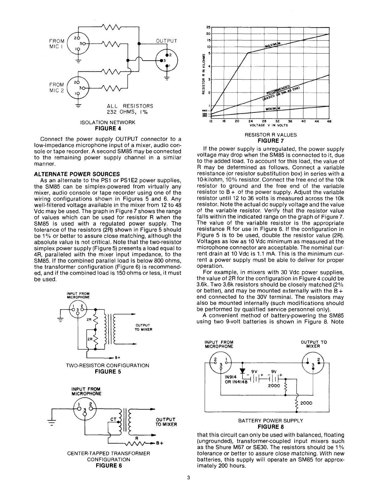
FROM
MIC
I
FROM
MIC
2
ALL
RESISTORS
232
OHMS,
I0/o
ISOLATION NETWORK
FIGURE
4
Connect the power supply OUTPUT connector to a
low-impedance microphone input of a mixer, audio con-
sole or tape recorder. A second SM85 may be connected
to the remaining power supply channel in a similar
manner.
ALTERNATE POWER SOURCES
As an alternate to the PSI or PSI E2 power supplies,
the SM85 can be simplex-powered from virtually any
mixer, audio ccnsole or tape recorder using one of the
wiring configurations shown in Figures 5 and 6. Any
well-filtered voltage available in the mixer from 12 to 48
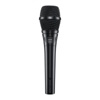
Vdc may be used. The graph in Figure
7
shows the range
of values which can be used for resistor
R when the
SM85 is used with a regulated power supply. The
tolerance of the resistors (2R) shown in Figure 5 should
be 1
O/O
or better to assure close matching, although the
absolute value is not critical. Note that the two-resistor
simplex power supply (Figure
5)
presents a load equal to
4R,
paralleled with the mixer input impedance, to the
SM85. If the combined parallel load is below 800 ohms,
the transformer configuration (Figure 6) is recommend-
ed, and if the combined load is 150 ohms or less, it must
be used.
INPUT FROM
MICROPHONE
n
OUTPUT
TO
MIXER
C
TWO-RESISTOR CONFIGURATION
FIGURE
5
INPUT FROM
MlCROPHObJE
OUTPUT
TO
MIXER
C
R
CENTER-TAPPED TRANSFORMER
CONFIGURATION
FIGURE
6
RESISTOR R VALUES
FIGURE
7
If the power supply is unregulated, the power supply
voltage may drop when the SM85 is connected to it, due
to the added load. To account for this load, the value of
R may be determined as follows. Connect a variable
resistance (or resistor substitution box) in series with a
10-kilohm,
10% resistor. Connect the free end of the 10k
resistor to ground and the free end of the variable
resistor to
B
+
of the power supply. Adjust the variable
resistor until 12 to 36 volts is measured across the
10k
resistor. Note the actual dc supply voltage and the value
of the variable resistor. Verify that the resistor value
falls within the indicated range on the graph of Figure
7.
The value of the variable resistor is the appropriate
resistance
R for use in Figure 6. If the configuration in
Figure 5 is to be used, double the resistor value
(2R).
Voltages as low as 10 Vdc minimum as measured at the
microphone connector are acceptable. The nominal cur-
rent drain at 10 Vdc is 1.1
mA. This is the minimum cur-
rent a power supply must be able to deliver for proper
operation.
For example, in mixers with 30 Vdc power supplies,
the value of 2R for the configuration in Figure
4
could be
3.6k. Two 3.6k resistors should be closely matched (2%
or better), and may be mounted externally with the
B+
end connected to the 30V terminal. The resistors may
also be mounted internally (such modifications should
be performed by qualified service personnel only).
A convenient method of battery-powering the SM85
using two 9-volt batteries is shown in Figure 8. Note
INPUT
FROM
OUTPUT
TO
MICROPHONE
MIXER
BATTERY POWER SUPPLY
FIGURE
8
that this circuit can only be used with balanced, floating
(ungrounded), transformer-coupled input mixers such
as the Shure M67 or
SE30. The resistors should be
1
O/O
tolerance or better to assure close matching. With new
batteries, this supply will operate an SM85 for approx-
imately 200 hours.