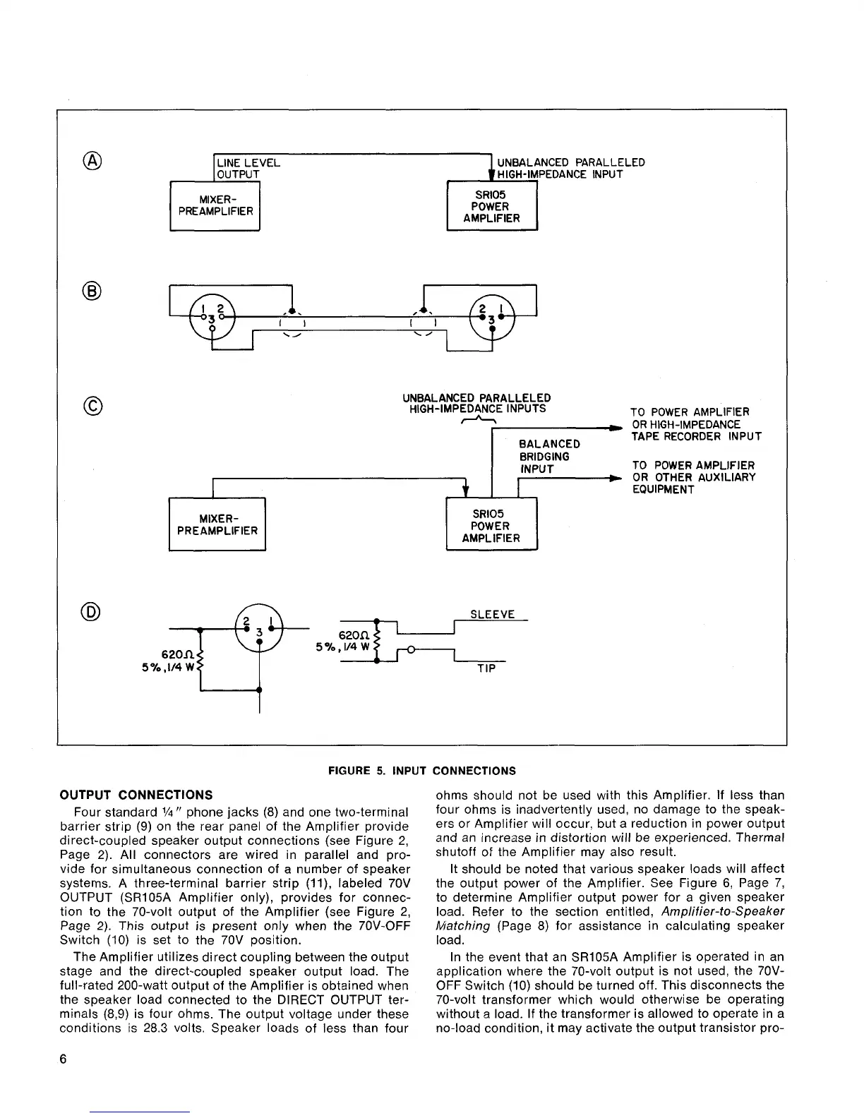
FIGURE
5.
INPUT CONNECTIONS
@
UNBALANCED PARALLELED
MIXER-
PREAMPLIFIER
POWER
AMPLIFIER
0
I
I
I
I
I
\/
\A
0
UNBALANCED PARALLELED
HIGH-IMPEDANCE INPUTS
A
TO POWER AMPLIFIER
-
-
OR HIGH-IMPEDANCE
OUTPUT CONNECTIONS
Four standard
1/4"
phone jacks (8) and one two-terminal
barrier strip (9) on the rear panel of the Amplifier provide
direct-coupled speaker output connections (see Figure 2,
Page 2). All connectors are wired in parallel and pro-
vide for simultaneous connection of a number of speaker
systems. A three-terminal barrier strip
(ll), labeled 70V
OUTPUT
(SR105A Amplifier only), provides for connec-
tion to the 70-volt output of the Amplifier (see Figure 2,
Page
2).
This output is present only when the 70V-OFF
Switch
(10)
is set to the 70V position.
The Amplifier utilizes direct coupling between the output
stage and the direct-coupled speaker output load. The
full-rated 200-watt output of the Amplifier is obtained when
the speaker load connected to the DIRECT OUTPUT ter-
minals
(8,9) is four ohms. The output voltage under these
conditions is 28.3 volts. Speaker loads of less than four
+
-
ohms should not be used with this Amplifier. If less than
four ohms is inadvertently used, no damage to the speak-
ers or Amplifier will occur, but a reduction in power output
and an increase in distortion will be experienced. Thermal
shutoff of the Amplifier may also result.
BALANCED
TAPE RECORDER INPUT
BRIDGING
INPUT TO POWER AMPLIFIER
I
OR OTHER AUXILIARY
EQUIPMENT
It should be noted that various speaker loads will affect
the output power of the Amplifier. See Figure
6,
Page 7,
to determine Amplifier output power for a given speaker
load. Refer to the section entitled, Amplifier-to-Speaker
Matching (Page
8)
for assistance in calculating speaker
load.
In the event that an
SRlO5A Amplifier is operated in an
application where the 70-volt output is not used, the
70V-
OFF Switch (10) should be turned off. This disconnects the
70-volt transformer which would otherwise be operating
without a load. If the transformer is allowed to operate in a
no-load condition, it may activate the output transistor
pro-
MIXER-
PREAMPLIFIER
SR105
POWER
AMPLIFIER
@
SLEEVE
6-TT-
5
570,114 W TIP