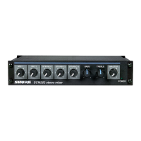
FIGURE A. SR110 FRONT PANEL
4
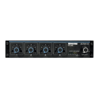
Output Impedances: 3. MASTER Volume Rotary Control/POWER OFF
Line Level
.
.
.
. .
..Balanced 120 ohms actual (for Switch-Adjusts level of total monitor output and
use with 600-ohm lines)
applies ac power to power supply.
Headphone
. . . .
.
.12 ohms actual (for use with 4-
4.
PHONES Output Jack-Provides for connection of
to 16-ohm headphones)
stereo or monophonic headphones for monitoring.
Mix Bus
. .
.
.
.
.
.
.
.5.6 kilohms 5. OUTPUT SELECTOR Slide Switch-Selects be-
Phasing
. . .
.
. . . . . . .Pins 1 through 8 of ACCESSORY
tween signal mixed in SRllO (MIXED INPUTS) or
connector are out of phase
mixed in
SRlO1 or SR109 (PROGRAM INPUT).
with,
and
pin 9
is
in phase
6. MONITOR OUTPUTS/LINE LEVEL Three-Circuit
with, pin 3 of
LlNE LEVEL out-
Phone Jacks (Two)-Provide balanced Monitor
put
&pin connector, tips of
Mixer output connection to power amplifier or
LINE LEVEL and PHONES recording equipment.
jacks,
and
tip
of
MIX
BUS
7. MONITOR OUTPUTS/LINE LEVEL 3-Pin Male
phono pin jack
Connector-Provides balanced Monitor Mixer out-
put connection to power amplifier or recording
Controls
. . . .
.
.
. . . . .Channel Volume: rotary, linear
taper; MASTER Volume:
equipment.
rotary, audio taper
8. ACCESSORY INPUT AND OUTPUT Cable
&
Multi-
Pin Male Connector-Provides for input connec-
Operating Voltage
.
.
.
SR110: 108-132 Vac, 50/60 Hz.
tions from Shure
SR101 or SR109 or similar equip-
SR110-2E:
105-1 25 or 21 0-250
ment.
Vac, 50/60 Hz.
9. ACCESSORY INPUT AND OUTPUT Multi-Pin
Fe-
Power
male Connector-Provides for connection of
addi-
Consumption
. .
.
.
.3 watts max. (Mixer only)
tional parallel-wired (tandem)
SRll 0s.
500
watts
max. (non-switched
10. MIX BUS Phono Jack-Provides common mix bus
ac receptacle)
(SR110 only)
when two
SRlOls or SRlO9s and two SRllOs are
Temperature:
to be operated in a common mix mode.
Operating
. . .
. .
. . . -7" to 54°C (+20° to 130°F) 11. Ac Grounded Line Cord-Connects ac power
Storage
.
.
. .
.
.
. . . -29" to 71°C (-20" to 160°F)
source to
SR110 power supply (SRllO only).
Dimensions
. . .
.
. . . .44.4 mm height X 483 mm 12. Non-Switched Ac Grounded Receptacle-Provides
width X 232 mm depth (1
3/4
in.
up to 500 watts of non-switched ac power to
ac-
X 19 in. X 9% in.)
cessory equipment
(SR110 only).
Weight
. .
. . .
.
.
.
.
.
. .3.9
kg (8 Ib, 8 oz)
13. AC (MAINS) POWER 3-Pin Connector-Connects
Finish
.
.
.
.
.
.
. .
.
.
.
.
.
Matte
black
unit to ac (mains) power source via supplied line
Installation
.
.
.
. .
. . . .Equipped for standard 19 in.
cord
(SR110-2E only).
(483 mm) audio rack mount-
14. VOLTAGE SELECTOR Slide Switch-Selects 105-
ing;
may be operated in
125V or 210-250V input power
(SR110-2E only).
optional-~105~' Carrying Case
(with
SR109)
General Operating Instructions
Certifications . . . . . . .Listed by Underwriters' Labora-
tories,
Inc.; listed by Canadian
Standards Association as
certified (SR110 only)
OPERATING
INSTRUCTIONS
Functional Description
(Refer to Figures A and B)
1. Individual Channel Volume Rotary Controls (Eight) 1. Using hardware provided, install
SR110 securely
-Control volume of each channel separately.
in standard 19 in. (483
mm) rack or optional A105A
2.
Power-On Indicator Lamp-Indicates ac power is Carrying Case (with SR109) prior to making
being applied to unit. electrical connections.
WARNING
To reduce the risk of fire or electric shock,
do not expose this appliance to rain or ex-
treme moisture.
-
AC
IMAINS!
POWER
*'c,,X?,I
-0.'
.*O
OL'?.,
?..Ll.i..
I,&
.dl
1,1*
.:,
,,
2
>>.>
IL'
IT
w
"1
$",*I
/
13
\
SR110-2E
ONLY
14
FIGURE
B.
SR110 REAR PANEL
 Loading...