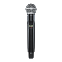
Shure U2 Hand-Held UHF Transmitter
Service Procedures25B1022 (AG) 17
Deviation Reference Voltage Adjustment
R286
U4 RECEIVER
AUDIO ANALYZER
TEST HEAD
RETAINING
RING
DC
BLOCK
20 dB
PAD
U201 U204
R227 for
G and later
board ver-
sions
R227 for
F and earlier
board versions
U2 Transmitter Audio Analyzer
Power: +3 Vdc Measurement: AC level
Gain: Minimum; for JB models set to MAX Output: 1 kHz
Filters:
Low-Pass (30 kHz): ON
High-Pass (400 Hz): ON
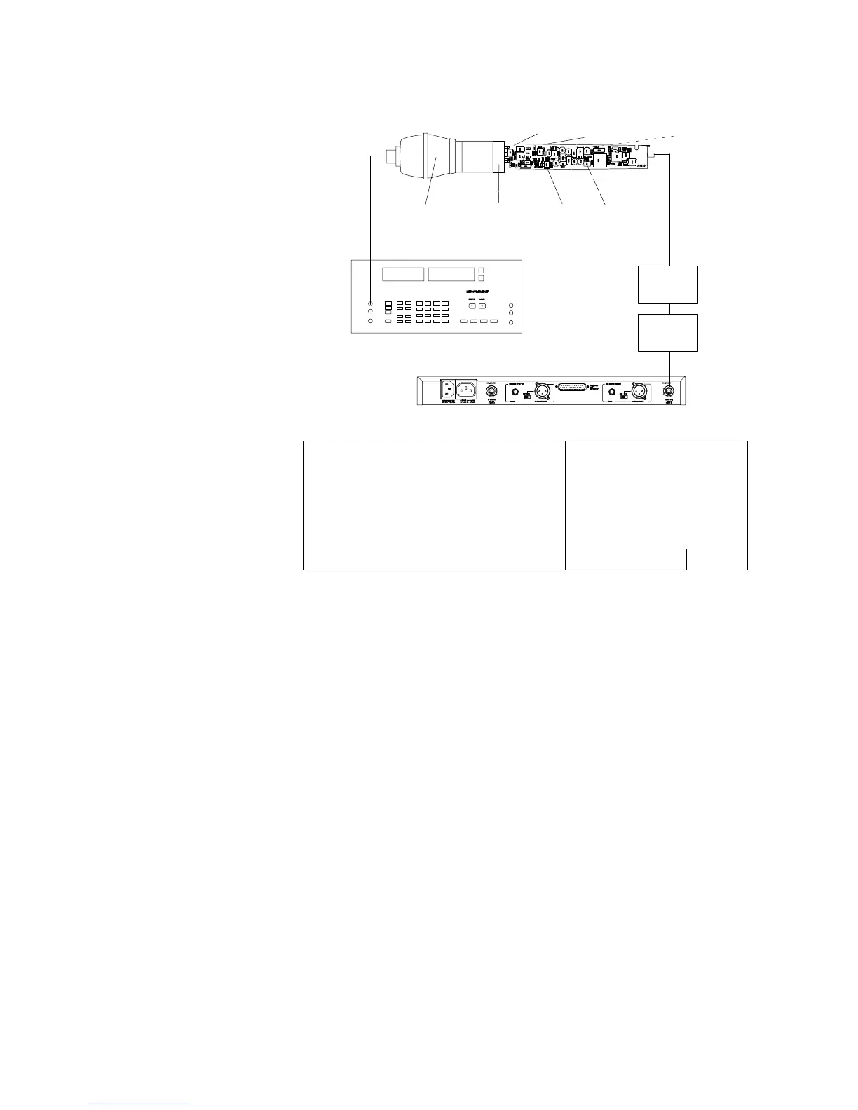
Figure 6. Microphone Test Head Configuration
1. Slide the U2 circuit boards into the supplied test head retaining
ring assembly.
2. Attach the microphone test head to the test head retaining ring
assembly.
3. Connect the audio analyzer output to the microphone test head
input. Connect the shield probe to the audio analyzer’s input.
4. Turn the U2 transmitter ON.
5. Adjust the audio analyzer output for 1 kHz to achieve a level of
-5.0 dBu (436 mV) at pin 7 of U201 on the transmitter. For JB
models, adjust the audio analyzer for 1 kHz and -65 dBu at the
input of the test head.
6. Connect the transmitter rf output to an antenna port on the U4
through a dc block and a 20 dB pad.
7. Connect the U4 unbalanced output to the audio analyzer’s input.
8. Adjust R227 until the audio analyzer reads the deviation
reference voltage determined in the previous test, ±0.05 dB
(±0.2 dB for JB models).
9. Disconnect the audio analyzer from the U4 unbalanced output.