Shure U2 Hand-Held UHF Transmitter
Service Procedures 25B1022 (AG)16
Audio Alignment
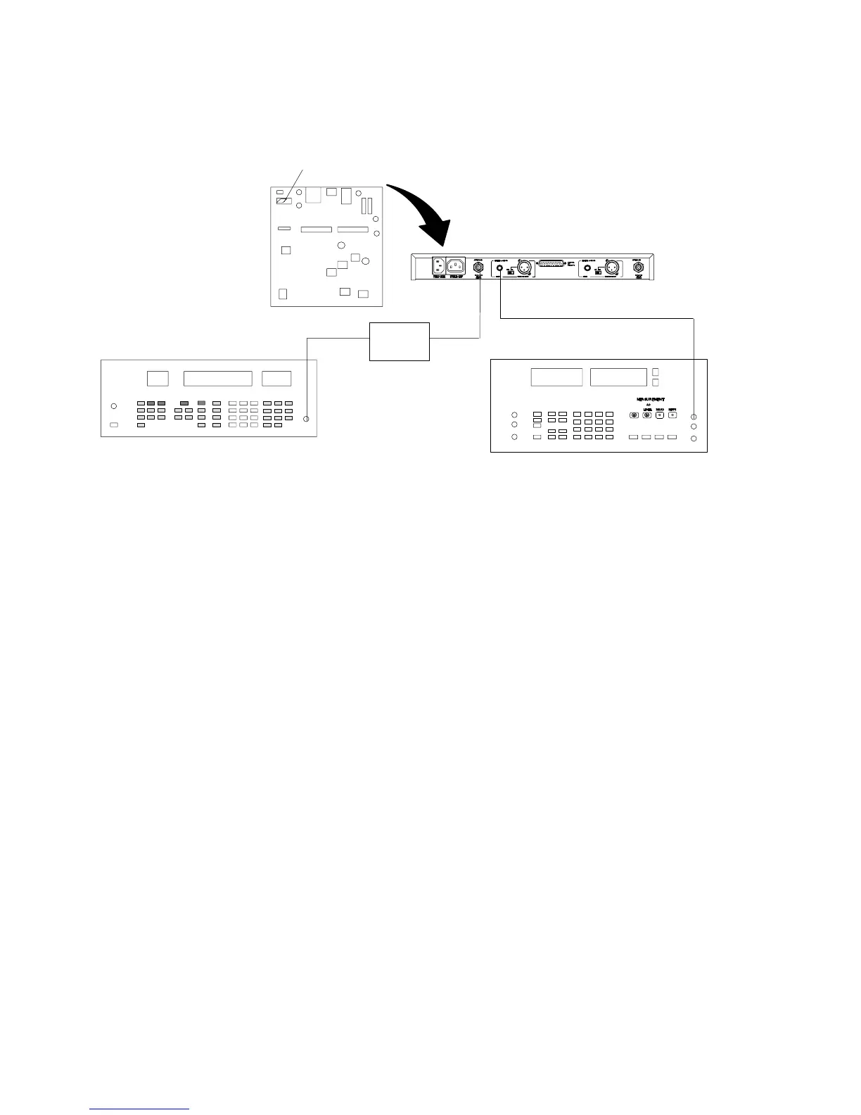
Deviation Reference Voltage
S201 (INSIDE U4)
U4 RECEIVER
RF SIGNAL GENERATOR
AUDIO ANALYZER
DC
BLOCK
U4 Receiver Audio Analyzer Rf Signal Generator
Output: Unbalanced Measurement: AC level INT: FM
Gain: Maximum Filters: INT: 1 kHz
Squelch: Mid Low-Pass (30 kHz): ON Output Amplitude: –50 dBm
Tone Key (S201): OFF High-Pass (400 Hz): ON
Figure 5. Deviation Reference Voltage Set-Up
1. Turn the U2 transmitter OFF.
2. Remove the cover of the U4 receiver to expose the pcbs.
3. Connect the rf signal generator to antenna port A or B on a U4
receiver. Make sure the dc block is on the rf signal generator.
4. Set the rf signal generator to the same frequency as the U2.
5. Set the rf signal generator internal FM tone to 1 kHz modulation.
6. Set the rf signal generator deviation to 45 kHz for UA, UB, MA,
MB, MC, and MD models; 40 kHz for KK models; and 5 kHz for
II models.
7. Set the rf signal generator amplitude to –50 dBm.
8. Turn the U4 receiver ON and set switch S201 inside the U4 to
the OFF position. This will disable the tone key function.
9. Set the output level of the U4 receiver to maximum.
10. Connect the voltmeter section of the audio analyzer to the
unbalanced output of the U4.
11. Verify that the voltage is 4.2 ± 0.5 dBu (1.26 ± 0.07 V) for UA, MA,
UB MB, MC, MD, and KK models, and –26.2 ± 0.5 dBu for II mod-
els. This is the deviation reference voltage.
12. Disconnect the rf signal generator from the U4 and move switch
S201 on the U4 to the ON position.
13. Turn OFF the rf output power from the rf signal generator.