1
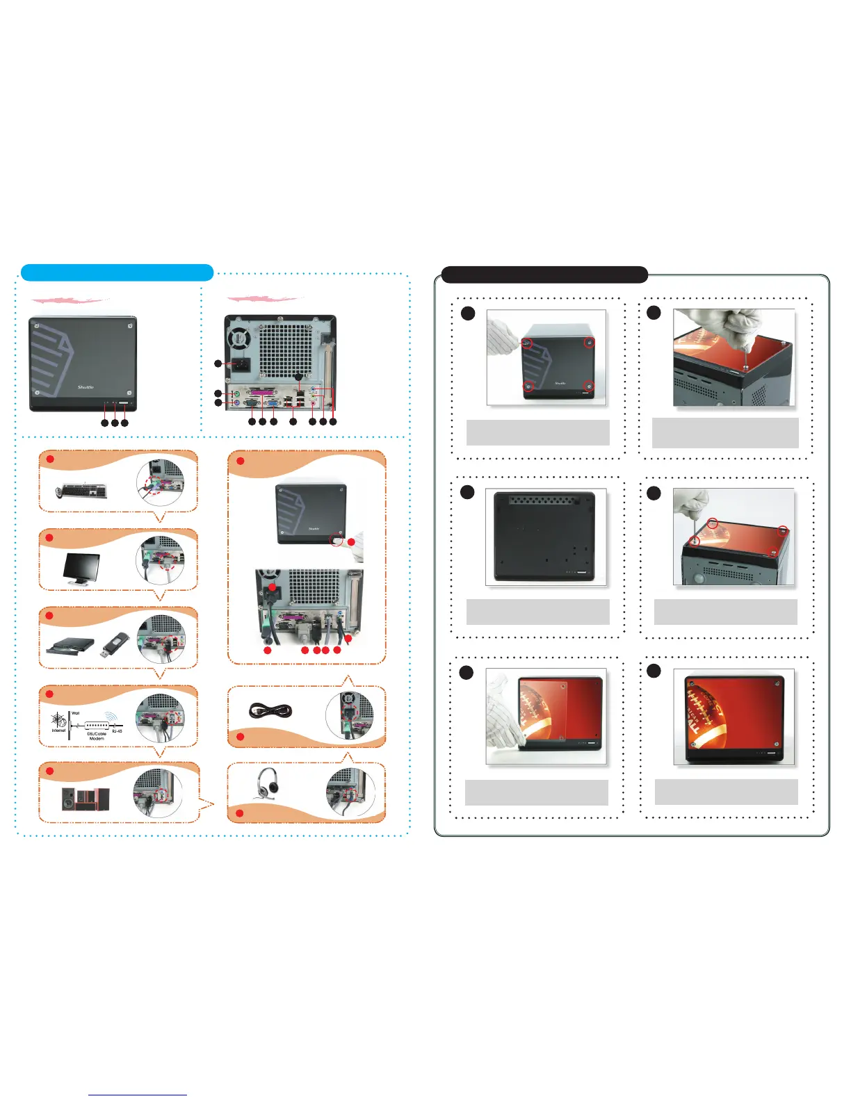
K45 System Quick Guide
【
English
】
F1. Power Switch
F2. Power LED
F3. HDD LED
B1
B2
B11
7
6
B5 B7B4 B6
B9
F3
F1
1
8
3
2
5
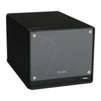
Front panel
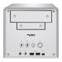
Back panel
B1. AC Power Socket
B2. PS/2 Mouse Port
B3. PS/2 Keyboard Port
B4. COM Port
B5. Parallel Port
B6. VGA Port
B7. USB Ports
B8. LAN Port
B9. MIC-In Port
B10. Front-Out (L/R) Port
B11. Line-In Port
B3
B8
B10
8
1
2
3 4
5
6
7
Customize Your Front Panel
【
English
】
Unfasten the front panel by removing
the four screws.
2
3
4
5
6
Remove both the transparent glass
and the image.
Align and correspond the transparent
glass and new image to screw holes
on the front of the machine.
Carefully screw back the four screws.
Insert the new image and cover back
the transparent glass on top.
Congraduation, you have your
customized image now.
Connecting Power
(AC Power Socket)
Connecting USB device
(USB Ports)
Connecting Speaker
(Front-Out Port)
Connecting Monitor
(VGA Port)
Connecting Keyboard and Mouse
(PS/2 Mouse, PS/2 Keyboard Port)
4
Connecting the Network
(LAN Port)
Powering on the system
(Power Switch)
Connecting Headphone & Microphone
(Front-Out & MIC-In Port)
Support 5.1 channels
F2