30
ENGLISH • Instructions manual
S 42
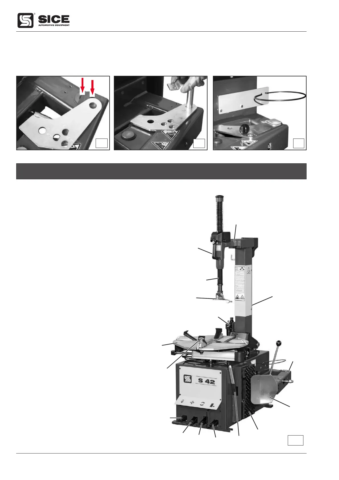
7. IDENTIFICATION OF PARTS (FIG. G)
1- Table top rotate pedal
2- Table top
3- Bead breaker (loosener) pedal
4- Bead breaker arm
5- Table top clamp opening/closing pedal
6- Wheel clamp
7- Tilting column pedal
8- Tilting column
9- Control arm handle
10- Hexagonal arm
11- Horizontal arm
12- Filter and lubricator
13- Rubber tyre rest
14- Bead breaker (loosener) blade
15- Tyre lever
16- Mounting/demounting head tool
2
1
3
4
5
6
7
8
9
11
12
13
14
10
16
15
G
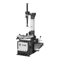
9) Fix the bracket (6, Fig. K/3) to the body of the machine using the screws supplied with the kit (see Fig. K/9).
Fit the grease cup support ring on the bracket.
10) Fit the adjuster pin (2. Fig. K/3) into the hole marked 0 on the stroke limiter.
K/7
K/8
K/9
 Loading...