21
Use and maintenance Manual AUTOMATIC GENSET CONTROL PANEL with GC310/GC350
Before supplying the Control Panel with the Mains voltage, ensure that:
- The data given in the paragraphs described above, regarding the installation, the electric
connection of the diagrams and the minimum sections suggested, have been observed.
- The GC310/GC350 controller has been set in OFF.
WARNING: in order to avoid whiplashes in the cables and not to damage the power devices in case
of short circuit, it is obligatory to fasten and lock all the power cables together with plastic ties once
connected to the switch and to the breaker.
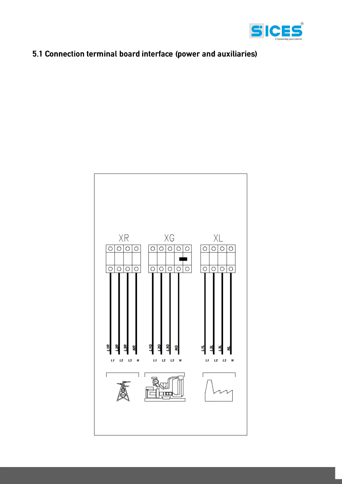
Below, see a diagram showing how the Control Panel interfaces to the plant. For the power
connections, we can distinguish 2 types: one with contactors (size 35÷80kVA) and the other with
motorized switch (size 100÷1580kVA). The auxiliary XA and XM terminal board is the same for the
two types.
Fig.1 – Connection of the power cables on the terminal board.
MAINS LINE GENSET LINE LOAD LINE