12 User’s Manual GC315xx-GC400xx
Different operation mode.
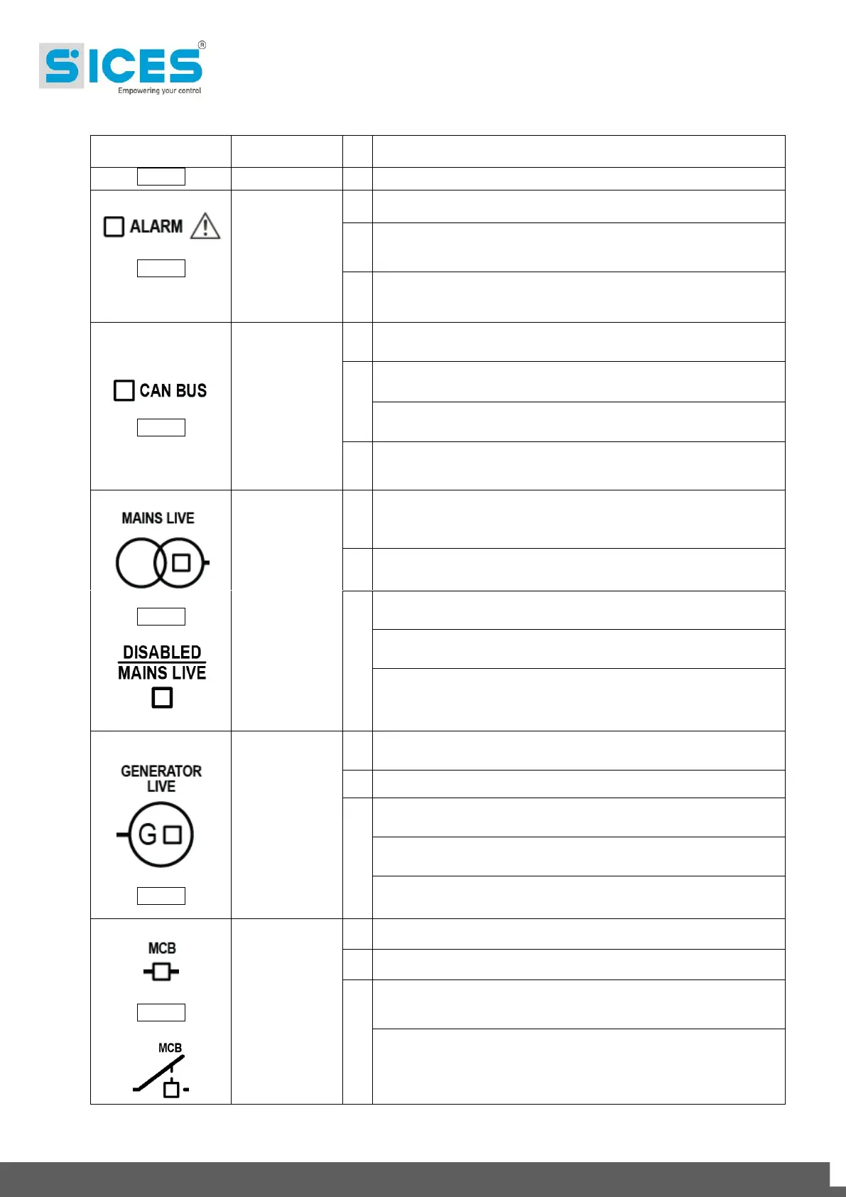
Indicates the presence of at least one lockout or power-off.
Signals at least one warning which has not yet been
acknowledged with the “ACK/ENTER” button.
Signals that the CAN-BUS interface is active and in ERROR-
ACTIVE mode. (J1939 or MTU)
Flashing at 25% ON signals a COM error (J1939 or MTU): the
port is in ERROR-PASSIVE mode.
Flashing at 75% ON signals a COM error (J1939 or MTU): the
port is in BUS-OFF mode.
Indicates that the CAN-BUS has been disabled.
Mains power is ON and stable in the tolerance range.
The MAINS SIMULATION digital input is enabled from the set
time.
The MAINS SIMULATION digital input is disabled.
Flashing at 50% during transition between the previous two
status.
Flashing at 25% the Mains power is on but below the tolerance
range.
Flashing at 75% the Mains power is on but over the tolerance
range.
Generator voltage and frequency are present and stead within
the tolerance range.
Generator voltage and frequency are not present.
Flashing at 50% during transition between the previous two
status.
Flashing at 25% ON - Power and frequency under tolerance
range.
Flashing at 75% ON - Power and frequency above tolerance
range.
The MCB switch is opened.
The MCB switch is closed.
Flashing at 25% ON if the KG is open after a closing command.
Flashing at 75% ON - If closed after an Open command.
 Loading...