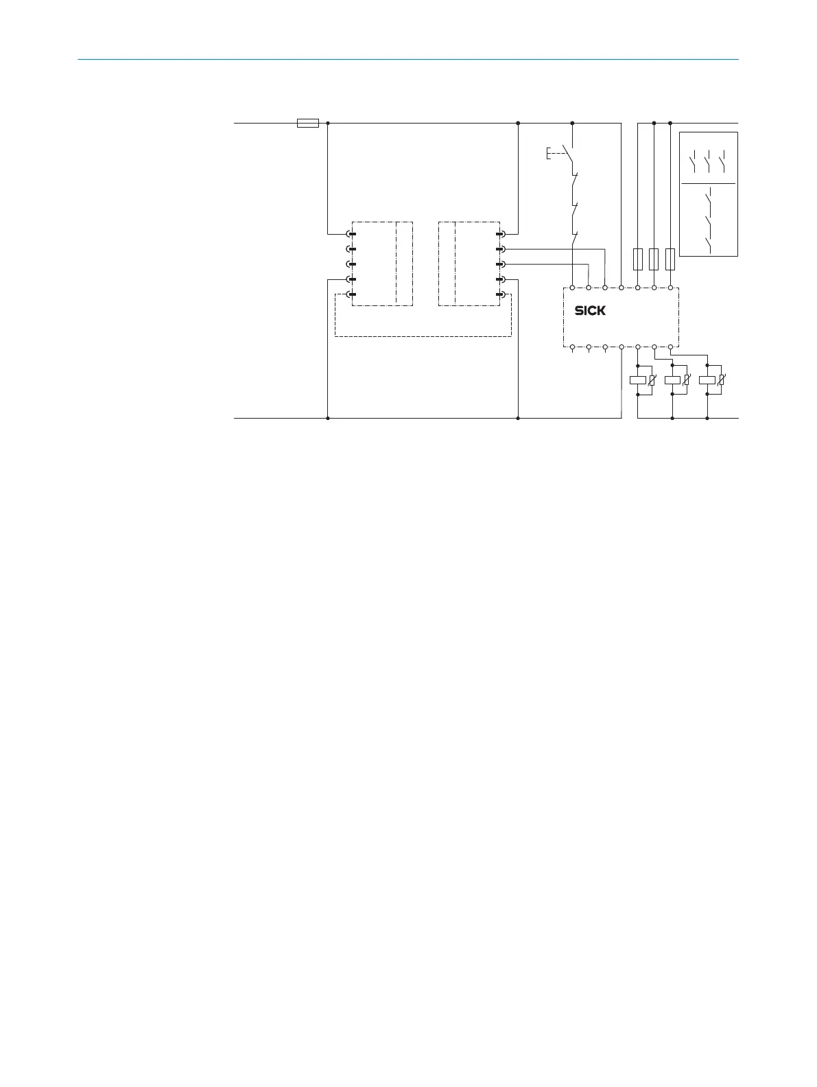
4.4.5 Connection diagrams
deTec4
1
2
4
3
5
2
)
3) PELV
r
System connection
+24 V DC
OSSD1
OSSD2
0 V
Com1
1
2
4
3
5
s
System connection
+24 V DC
In2
In1
0 V
C
om1
F2 F1F3
+24 V DC
0 V DC
K3 K2 K1
E243842/01/2019-10-11
F0
L+
L–
S1
k2
k1
z
k3
z
1)
k1 k2
x1 x2
x1 x2
k3
y1
y1
k3
k1
k2
R1 Y1 Y2 243
4A2 14
S1 I1 I2 2333A1 13
RLY3-OSSD3
Figure 4: ReLy OSSD3 connection diagram
4.5 Testing plan
The safety relay must be thoroughly checked by appropriately qualified safety personnel
dur
ing commissioning, after modifications, and at regular intervals, see "Thorough
check", page 21.
The regular thorough checks serve to assess the effectiveness of the safety relay and to
identify defects as a result of modifications or other influences (e.g., damage or manip‐
ulation).
The manufacturer and user must define the type and frequency of the thorough checks
on the machine on the basis of the application conditions and the risk assessment.
Determination of the thorough checks must be documented in a traceable manner.
4.5.1 Minimum requirements for the regular thorough check
The following thorough checks must be carried out at regular intervals:
•
T
horough check of the housing for damage
•
Thorough check of the cables for damage
•
Thorough check of the safety relay for signs of misuse or manipulation
•
Thorough check of the safety function
The minimum test interval depends on the applicable safety capability of the overall
application, see table 5, page 24.
4 P
ROJECT PLANNING
14
O P E R A T I N G I N S T R U C T I O N S | ReLy OSSD3 8023925/2019-10-11 | SICK
Subject to change without notice