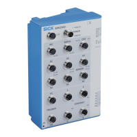
The SICK SIM2500 Sensor Integration Machine is a programmable device designed to open up new possibilities for application solutions within the SICK AppSpace ecosystem. It functions as a central unit for reading, merging, evaluating, archiving, and transmitting data from various SICK sensors, such as LiDAR scanners and cameras. The device can process this data into a point cloud, enabling advanced machine vision applications.
Function Description:
The SIM2500 is equipped with a high-performance multi-core processor, a fast FPGA coprocessor, and a highly synchronous FPGA I/O, allowing for real-time image (pre)processing and handling of input and output signals. It integrates the HALCON image processing library and the open SICK AppSpace software platform, facilitating the development of customized application programs for demanding 2D and 3D machine vision tasks.
The device supports various sensor integrations:
- 2D and 3D Cameras: Four fast Ethernet interfaces with Power over Ethernet (PoE) are available for connecting 2D or 3D cameras, including SICK picoCam, midiCam, and any GigE Vision/GenICAM compliant cameras.
- IO-Link: Other sensors, such as those for distance and height measurement, can be integrated via IO-Link.
- CAN Sensor Network: The SIM can be integrated into a SICK CAN sensor network.
- Fieldbus and Ethernet Interfaces: OPC-UA and MQTT protocols are supported for data preprocessing in "dual talk" (edge computing) for controllers and cloud computing.
Human-Machine Interface (HMI) and data visualization features are accessible on any browser-enabled notebook, PC, or tablet. Applications are created using SICK AppStudio SDKs and HDevelop from MVTec (for HALCON).
Important Technical Specifications:
- Embedded Hardware Architecture:
- 8-core ARM Cortex-A72 CPU with NEON accelerator.
- FPGA for image (pre-)processing.
- FPGA for I/O handling.
- Dedicated fieldbus controller.
- Software:
- Programmable within the SICK AppSpace environment.
- SICK Interface & Algorithm API.
- Integrated HALCON image processing library.
- Memory:
- Random Access Memory: 4 GB DDR4.
- Flash memory: 7 GB eMMC (5 GB available for applications).
- Optional memory card: Industry-grade microSD memory card (flash card), max. 32 GB.
- Power Supply:
- Power consumption: Typ. 45 W (without connected sensors).
- Power output: Max. 140 W total (all connections).
- Voltage supply: 24 V DC, ±10% SELV in accordance with EN 61010, also applies to digital inputs.
- Operating current: Must be limited by external power supply unit to max. 8 A.
- Output Current:
- SENSOR S1-S6, I/O: ≤ 100 mA, on digital output pins.
- SENSOR S1-S4: ≤ 1 A, on power supply pins.
- SENSOR S5-S6: ≤ 2.5 A, on power supply pins. Switching times when using the "Connector.Power.Gate" API: Rise time/fall time/delay < 10 µs, max. frequency: 10 kHz.
- CAN: ≤ 3.2 A, on power supply pins.
- SERIAL: ≤ 1 A, on power supply pins.
- INC: ≤ 0.5 A, on power supply pins.
- I/O: ≤ 500 mA, on power supply pins.
- Interfaces:
- I/O: Universal port with configurable inputs/outputs, opto-decoupled inputs, and voltage supply for peripherals.
- POWER: Voltage supply input.
- INC: One incremental encoder In/Out or RS-422, with voltage supply for peripherals. Max frequency: 2 MHz.
- SERIAL: One RS-232/RS-422/RS-485 or one INC In/Out, with voltage supply for peripherals. Max data transmission rates: RS-232: 115.2 kBaud, RS-422/RS-485: 2 MBaud.
- CAN: Connection for SICK CAN sensor network (receiver/transceiver), with voltage supply for peripherals.
- SENSOR 1-4: Four sensor connections with digital inputs/outputs and voltage supply. Can be used as IO-Link master connections (1x master available per connection). Digital inputs/outputs are switchable. Max. output 100 mA, min. high output logic level VCC-3V, max. low output logic level 3V. Max. IO-Link output frequency 230 kHz. Max. IO input frequency 30 kHz.
- SENSOR 5-6: Two sensor connections with two configurable inputs/outputs, one dedicated input, and voltage supply. S6 is provided to supply and control the fan. Max. 2.5 A output for supply voltage.
- FIELDBUS: Two Ethernet-based fieldbus interfaces (PROFINET and EtherNet/IP support, EtherCAT under development). Data transmission rates: 10/100 Mbit/s.
- ETHERNET: Four Ethernet connections with PoE (PoE supply voltage factory deactivated, PoE according to class 4). Transmission rates: 0.01; 0.1; 1, 2.5 Gb/s. Jumbo frame support required with Ethernet switches. Preset IP addresses: ETH1: 192.168.0.1, ETH2: 192.168.1.1, ETH3: 192.168.2.1, ETH4: 192.168.3.1.
- USB: Micro-B connection for configuration/diagnostics/firmware update.
- Mechanical and Electrical:
- Housing material: Aluminum die cast.
- Housing color: Light blue (RAL 5012).
- Protection class: III.
- Weight: 1995 g.
- Dimensions (W x D x H): 176 x 83 x 196 mm.
- Enclosure rating: IP65 (requires blind plugs in unused connections).
- Ambient Conditions:
- Operation site: Use inside buildings.
- Height position: max. 2,000 m.
- Contamination rating: 1.
- Ambient operating temperature: 0 °C ... +50 °C.
- Storage temperature: -20 °C ... +70 °C.
- Permissible relative humidity: 90%, non-condensing.
- Electromagnetic Compatibility: IEC 61000-6-2:2016 / EN IEC 61000-6-2:2019, IEC 61000-6-3:2020.
- Vibration Resistance: IEC 60068-2-6:2007.
- Shock Resistance: IEC 60068-2-27:2008.
- Electrical Safety: IEC 61010-1:2010 + Cor.: 2011, IEC 61010-2-201:2017.
Usage Features:
- Mounting: The device can be mounted horizontally using a mounting rail or vertically suspended/horizontally positioned using adapter plates. Self-locking or lock nuts are recommended for mounting sites exposed to vibrations.
- Electrical Installation: Requires screened data cables with twisted-pair wires and EMC-compliant layouts. All grounding points must have the same ground potential, connected via the functional ground connection with a low impedance. Only operate with the specified supply voltage, meeting SELV requirements (EN 61010).
- Commissioning: Preparatory commissioning involves placing the device on a non-slip base, connecting peripheral devices, network, voltage supply, and the M12 fan plug to SENSOR port S6. An automatic, intelligent fan control starts after device start-up. Fan control at S6 can be deactivated if the port is used for other applications, allowing connection to S1-S4 or an external 24V supply.
- Status LEDs: The device features various LEDs (Dev RDY, Sys RDY, Result, Funct 1, Funct 2, Remote, BF/ERR/SF/RUN, Pwr/Act, Link, Act, PoE) to indicate operational status, connection status, and potential errors. These indicators are crucial for routine inspection and troubleshooting.
Maintenance Features:
The SIM2500 is designed for maintenance-free operation, but preventive tasks are recommended based on ambient conditions and climate:
- Regular Checks:
- Check device and connecting cables for damage at regular intervals.
- Clean housing, especially cooling ribs and fan, to ensure proper heat dissipation (using a dry towel or industrial vacuum cleaner, no cleaning agents). Recommended at least every 6 months for fans.
- Check that all unused connections are sealed with protective caps.
- Cleaning: Improper cleaning can lead to equipment damage. Only recommended cleaning agents and tools should be used, and sharp objects must be avoided.
- Disposal: If the device can no longer be used, it must be disposed of in an environmentally friendly manner in accordance with country-specific waste disposal regulations. The device should be allowed to cool down before decommissioning. Separate recyclable materials by type and place them in recycling containers.