O P E R A T I N G I N S T R U C T I O N S
UE10-3OS
Expansion module for basic
devices
en
SICK AG • Industrial Safety Systems
ErwinSick-Straße 1
D-79183 Waldkirch • www.sick.com
8009656/YSS0/2016-03-17 • REIPA/XX
Printed in Germany (2016-03) • All rights reserved •
Subject to change without notice
1 Scope
These operating instructions are only applicable to the
UE103OS basic device expansion modules with the
following entry on the type label in the field Operating
Instructions: 8009656
You will find the device’s date of manufacture on the
type label in the field Date Code in the format yywwxxxx
(yy = year, ww = calender week, xxxx = serial number).
These operating instructions are original operating
instructions.
2 On safety
This chapter deals with your own safety and the safety
of the equipment operators.
Please read this chapter carefully before working
with the UE103OS or with the machine protected
by the UE103OS.
2.1 Qualified safety personnel
The UE103OS expansion module must only be
installed, commissioned and serviced by qualified
safety personnel.
Qualified safety personnel are defined as persons
who …
have undergone the appropriate technical training
and
have been instructed by the responsible machine
operator in the operation of the machine and the
current valid safety guidelines and
have access to the operating instructions of the
UE103OS expansion module and have read and
familiarised themselves with them.
2.2 Applications of the device
The UE103OS expansion module can be used:
in accordance with EN ISO 13 849 up to PL e and
category 4
in accordance with EN 62 061 to SILCL3
in accordance with IEC 61 508 up to SIL3
The actual performance level or SIL claim limit achie-
ved depends on the external circuit, the design of the
wiring, the selection of the control switch and its place-
ment on the machine.
The UE10-3OS expansion module has been evaluated
to UL 508.
The UE103OS expansion module is used for:
electro-sensitive protective equipment (ESPE) with mo-
nitored active output signal switching device (OSSD):
single-channel, dual-channel (in accordance with
IEC 61 4961)
safety devices with monitored semiconductor outputs,
e.g. Flexi Classic and Flexi Soft
The UE103OS has no restart interlock and no external
device monitoring.
2.3 Correct use
The UE103OS expansion module must be used only as
defined in section 2.2 “Applications of the device”.
It must be used only by qualified safety personnel and only
on the machine where it has been installed and initialised
by qualified safety personnel in accordance with the opera-
ting instructions. If the device is used for any other purposes
or modified in any way — also during mounting and installa-
tion — any warranty claim against SICK AG shall become
void.
2.4 General safety notes and protective
measures
Pay attention to the safety notes and protective
measures!
Please observe the following items in order to en-
sure the correct use of the UE103OS expansion
module.
During the mounting, installation and usage of
the expansion module, observe the standards
and directives applicable in your country.
The national/international rules and regulations
apply to the installation, commissioning, use and
periodic technical inspection of the expansion
module, in particular:
– Machinery Directive
– Work Equipment Directive
– EMC directive
– the work safety regulations and safety rules
Manufacturers and operators of the machine on
which a expansion module is used are respon-
sible for obtaining and observing all applicable
safety regulations and rules.
The tests must be carried out by qualified safety
personnel or specially qualified and authorised
personnel and must be recorded and documen-
ted to ensure that the tests can be reproduced
and retraced at any time by third parties.
The operating instructions must be made avai-
lable to the operator of the machine where the
UE103OS is used.
The machine operator is to be instructed in the
use of the device by qualified safety personnel
and must be instructed to read the operating
instructions.
2.5 Environmental protection
Disposal of unusable or irreparable devices must always
occur in accordance with the applicable country-specific
waste-disposal regulations (e.g. European Waste Code
16 02 14).
3 Product description
The related actuators on the machine or system can be
safely shut down using the expansion module’s output
signal switching contacts.
The switching of the semiconductor outputs on the up-
stream basic devices controls the internal relays via the two
separate input circuits. The enable current paths are used
as safe outputs. The signalling current path is not a safe
output. The feedback current path is used as external
device monitoring for the monitoring by the basic device.
In order to attain SIL3/PL e, connect the external
device monitoring!
In order to reach SIL3/PL e, an external diagnosis
with DC K 99 % must be applied (i.e. the external
device monitoring must be connected).
Please also read the notes in chapter 11
“Application examples”.
Status indicators
Display Meaning
K1 Green Channel 1 switched
K2 Green Channel 2 switched
4 Mounting
Mounting only with enclosure rating IP 54 or
better!
The expansion module is only allowed to be mount-
ed in the control cabinet. The control cabinet must
at least comply with enclosure rating IP 54.
Mounting in accordance with EN 50 274.
The modules are located in a 22.5 mm wide modular
system for 35 mm mounting rails as per EN 60 715.
5 Electrical installation
Note:
All external switching elements and their wiring must
withstand an ampacity, maximal short-circuit load of
I
max
= 1000 A (according to EN 60947-5-1).
Switch the entire machine/system off line!
The voltage supply must satisfy the regulations for extra-
low voltages with safe isolation (SELV, PELV) for over-
voltage category II as per EN 60 664 and EN 50 178.
Note:
Overvoltage category III can be achieved if the contact
circuits Y1/Y2 and 41/42 are operated in the same cir-
cuit as the upstream OSSDs (safety extra-low voltage).
For installation in environments with overvoltage cate-
gory III, external protection elements must be used.
All connections, wiring and cable runs must comply with
the required category as per EN ISO 13849 and
EN 62 061 (e.g. cables laid with protection, individually
sheathed cable with screen etc.).
Always connect inputs B2 and B4 to the 0V potential of
the supply voltage for the basic devices.
To protect the contact outputs on the UE103OS and to
increase the service life, the loads connected must be
equipped with, e.g., varistors and RC circuits. Please also
note that the selection of the arc suppression can in-
crease the total response time of the safety function.
The output signal switching devices and the external
device monitoring (EDM) must be wired in the control
cabinet.
To prevent the welding of the contacts on the built-in
relay, an overcurrent protection device with max. 6 A
short-circuit protection (duty class gG) is to be integrated
into the current paths (see Fig. 2, enable current path
fuse F2/F3/F4).
Pin assignments
Terminal Description
B1 Input circuit 1
B3 Input circuit 2
B2 0 V
B4 0 V
Y1-Y2
Feedback current path (for usage as
external device monitoring)
13-14 Enable current path 1
23-24 Enable current path 2
33-34 Enable current path 3
41-42 Signalling current path (not safe)
Single-channel operation
A jumper is to be connected between B1 and B3. The semi-
conductor output on the basic device is to be connected to
B1; 0 V on the basic device is to be connected to the con-
tacts B2 and B4.
Dual-channel operation
The semiconductor outputs on the basic device are to be
connected to B1 and B3; 0 V on the basic device is to be
connected to the contacts B2 and B4.
6 Commissioning and regular
tests
Commissioning requires a thorough check by
qualified safety personnel!
Before you operate a system protected by the
expansion module for the first time, make sure that
the system is first checked and released by
qualified safety personnel.
Please read the notes in chapter 2 “On safety”.
Observe the relevant laws and national
regulations.
Check the hazardous area!
Ensure there is nobody in the hazardous area
before commissioning.
Secure the hazardous area against entry.
Regular inspection of the protective devices by qualified
safety personnel
Check the system following the inspection intervals
specified in the national rules and regulations.
– Each safety application must be checked at an interval
specified by you.
– The effectiveness of the protective devices must be
checked daily by a specialist or by authorised
personnel.
If changes have been made to the machine or the pro-
tective device, or the expansion module has been
changed or repaired, you must again thoroughly check
the entire safety application.
7 In the event of faults or errors
Cease operation if the cause of the malfunction
has not been clearly identified!
Stop the machine if you cannot clearly identify or
allocate the error and if you cannot safely rectify
the malfunction.
Complete function test after rectification of
fault!
After rectifying a fault, perform a complete
function test.
8 Ordering information
8.1 Systems
Part Part number
(type code)
UE103OS for 24 V DC
with screw type terminals
6024917
(UE10-3OS2D0)
UE103OS for 24 V DC
with removable terminals
6024918
(UE10-3OS3D0)
UE10-3OS for 24 V DC
with spring terminals
1028303
(UE10-3OS4D0)
9 Compliance with EU
directives
EU declaration of conformity (excerpt)
The undersigned, representing the following manufac-
turer herewith declares that the product is in conformity
with the provisions of the following EU directive(s)
(including all applicable amendments), and that the
respective standards and/or technical specifications
are taken as the basis.
Complete EU declaration of conformity for download:
www.sick.com.
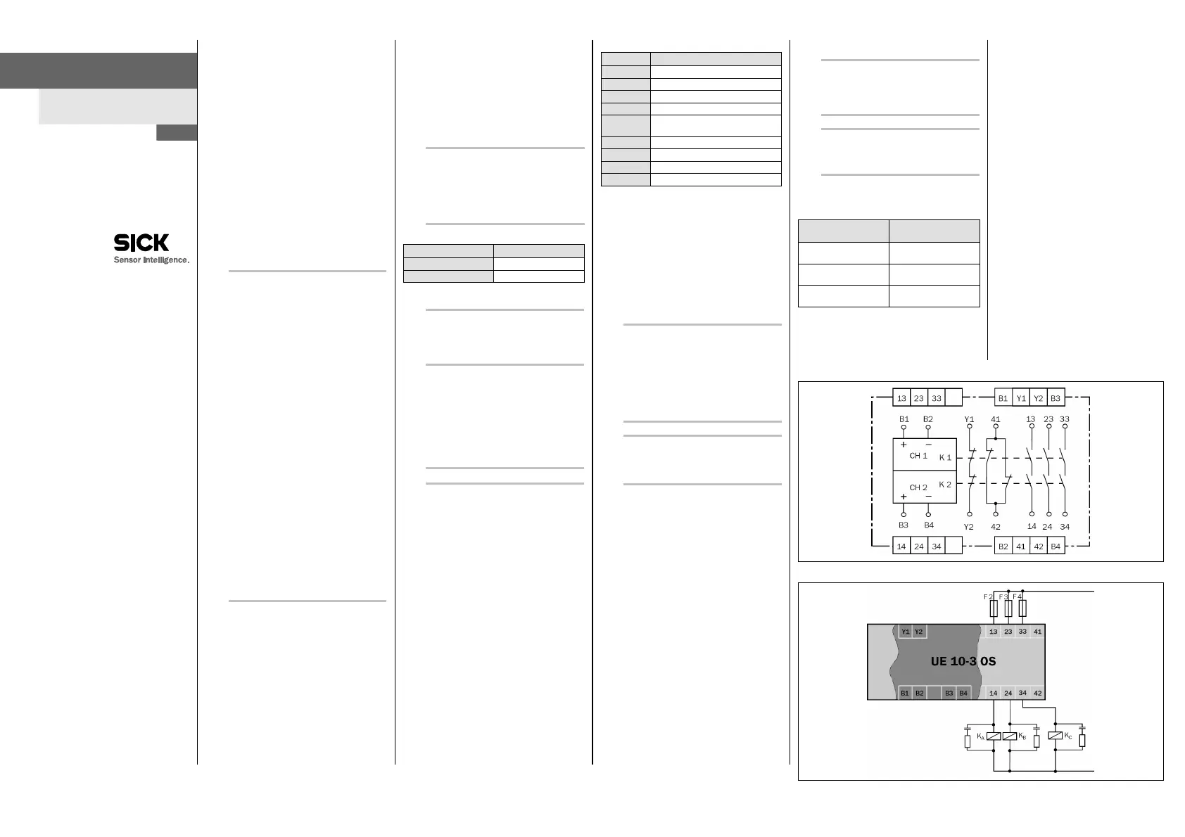
10 Internal circuitry
Fig. 1: Internal circuitry UE103OS
Fig. 2: Basic circuit UE103OS
 Loading...


