12
Siemens AG
DEUTSCH / ENGLISH
Fig. 4 Kühlmittelanschluß / Coolant connection
Typ
Type
± 0,75 I/min
1PH410.
1PH413.
1PH416.
7 bar
1900 W
2600 W
3000 W
2750 W
3500 W
4100 W
4500 W
4600 W
5400 W
6200 W
6 I/min
6 I/min
6 I/min
8 I/min
8 I/min
8 I/min
8 I/min
10 I/min
10 I/min
10 I/min
G 3/8
G 1/4
G 1/2
Kühlwasserstrom
Cooling water flow rate
max. zulässiger Druck
Maximum permissible
pressure
Kühlleistung
Cooler efficiency
Anschluß
Connection
1
3
5
42
7
6
6
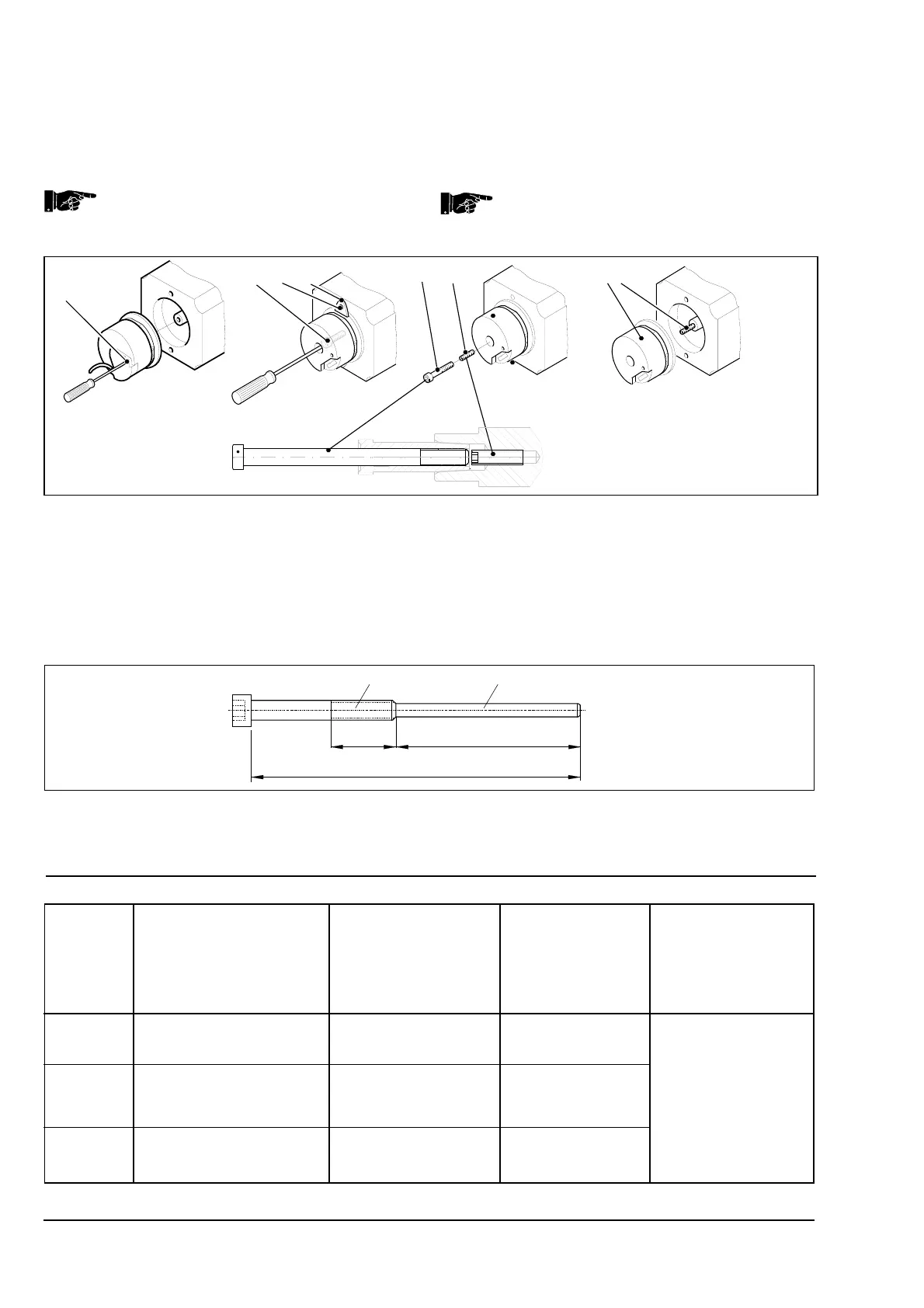
Fig. 3.2: Abdrücken des Gebers mit Gewindestift
und Schraube oder Sonderschraube
1 Schraube zur Deckelbefestigung
2 Mittelschraube zur Befestigung Geber
3 Schraube zur Befestigung Drehmomentstütze
4 Drehmomentstütze
5 Abdrückschraube
6 Gewindestift
7 Geber
Fig. 3.2: Pulling off the transducer with the
threaded pin and screw or special screw
1 Centre screw for holding transducer
2 Central screw holding the transductor
3 Screw fixing the holding plate
4 Holding plate
5 Pulling-off screw
6 Threaded pin
7 Transducer
>10 m m
56 m m
100 m m
M6 Ø4 mm
8. Stecker Geberanschluß abziehen. Geber (7, Fig. 3.2) abziehen
und ablegen.
9. Schraube (5, Fig. 3.2) und Geberstift (6, Fig. 3.2) entfernen.
Statt Gewindestift (6, Fig. 3.2) und Schraube (5, Fig. 3.2)
kann folgende Sonderschraube verwendet werden
(nicht im Lieferumfang)!
8. Pull the plug out of the transducer connector. Draw the transducer
off (7, Fig. 3.2) and lay it down.
9. Remove the screw (5, Fig. 3.2) and the threaded pin
(6, Fig. 3.2).
Instead of the threaded pin (6, Fig. 3.2) and the
screw (5, Fig. 3.2), the following special screw can be
used (not within the scope of the delivery)!
Fig. 3.3: Sonderschraube für Demontage
ERN 1381.001 und ROD 431.001
Fig. 3.3: Special screw for disassembling the
ERN 1381.001 and ROD 431.001