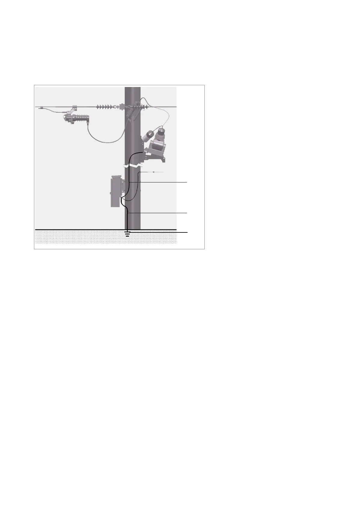
The VT mounting frame must be connected to the RCU cubicle earth stud and to ground. If the
VT has an earth screen it must be grounded to the frame.
If the primary of the VT is fitted with surge arrestors they must be grounded to the VT mounting
frame.
It is the user’s responsibility to provide the earth wire and to fit in accordance with the applicable
safety guidelines.
1 Earth wire from VT to RCU
2 Earth wire
3 Earth
Fig. 31 RCU and Voltage Transformer Earthing Diagram
5.11 Radio Installation
Each different radio or modem will require slightly different installation methods to be developed.
Refer page 19 for allowable radio sizes. A generic approach is as follows:
1. Remove the radio tray from the RCU.
2. Remove the radio mounting plate from the radio tray by unscrewing the M5 nuts using
an 8mm socket.
3. The user is to arrange the radio/modem items, including antenna surge arrester in a
appropriate way on the mounting plate. Mark all hole locations required.
4. Drill holes and deburr edges as required.
5. Assemble radio/modem items to mounting plate. User to provide fasteners etc.
6. Install the mounting plate back onto the radio tray and tighten in place with the M5
nuts using the 8 mm socket. Torque to 3 Nm.
7. Fit the radio tray back into the RCU enclosure taking account of antenna connections
and connection to electronics compartment.
8. If an antenna surge arrestor is fitted (recommended) ground it to the M6 earth stud in
the cubicle.
9. Connect the appropriate radio cable (user to supply or can purchase from Siemens –
Contact Siemens sales representative) to the radio and the appropriate port on the
RCU electronics enclosure.