3-2
9947-921-0B
2003-09-12
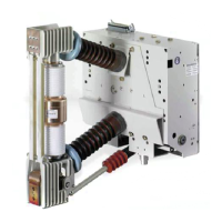
3.1.2 Полюс с двумя прерывателями
Полюс выключателя (19.) состоит из прочного
каркаса, в котором расположены друг над другом
два прерывателя (30.), подвижные вводы которых
расположены друг против друга. Каркас состоит из
полюсной пластины со стороны привода (15.), из
трех закрепленных на ней опорных изоляторов
(16.), на которых расположены оба держателя
прерывателей (20., 40.) и передаточный механизм
на среднем полюсе (39.), а так же из четырех
изолирующих распорок (28.), которые попарно
связывают верхнюю или нижнюю опоры преры-
вателей с полюсным передаточным механизмом.
Опоры прерывателей одновременно представляют
собой внешние вводывыключателя. В выключа-
телях 3АН4756 и 3АН4757 параллельно прерыва-
телям необходимо подключить уравнивающие
конденсаторы (38.) емкостью по 150 pF каждый,
чтобы уравновесить нагрузку по напряжению
прерывателей. Изолирующая приводная тяга (48.)
передает переключающее движение с привода на
полюсный передаточный механизм (39.).
В передаточном механизме горизонтальное движе-
ние изоли рующ ей приводной тяги распределяется
на оба прерывателя через рычажную кинематику и
далее переводится под прямым углом в
вертикальный ход контактов прерывателей. У
каждого вакуумного прерывателя есть своя
притирающая пружина (49.). Направляющие рычаги
обеспечивают прямолинейный вертикальный ход
подвижных токопроводящих штоков прерывателей.
Оба прерывателя электрически соединены между
собой в полюсном передаточном механизме
боковыми гибкими шунтами.
3.1.2 Pole with two interrupters
The circuit-breaker pole (19.) consists of a stable frame
in which the two interrupters (30.) are arranged one
upon another and with the moveable terminals opposite
to another. The frame consists of the pole plate (15.) on
the operating mechanism end, the three post insulators
(16.) secured to it, which bear the two interrupter sup-
ports (20., 40.) or the middle pole gearing (39.), and the
four insulating struts (28.) which join the top or bottom
interrupter support to the pole gearing in pairs. The in-
terrupter supports simultaneously represent the outer
terminals of the circuit-breaker. In the case of the
3AH4756 and 3AH4757 circuit-breakers, grading capa-
citors (38.) with capacitance values of 150 pF each are
connected in parallel with the interrupters to even out
the voltage load on the interrupters. An operating rod
(48.) transfers movement of the circuit-breaker from the
operating mechanism to the pole gearing (39.).
In the pole gearing, horizontal movement of the opera-
ting rod is distributed over the two interrupters by me-
ans of a lever system and is diverted rectangularly to a
lifting motion of the interrupters’ contacts. Each inter-
rupter is assigned a contact pressure spring (49.) of its
own. Guide levers ensure a rectilinear lifting movement
of the moveable terminal bolts of the interrupters. Both
interrupters are linked electrically by lateral flexible con-
nectors in the pole gearing.

 Loading...