9947-921-0B
2003-09-12
3-1
3 Описание
3.1 Конструкция
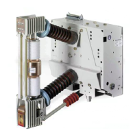
Тяговый выключатель 3АН47 по своему внешнему
устройству отличается наличием полюса с одним
вакуумным прерывателем и полюса с двумя
размещенными друг над другом прерывателями.
Базовая конструкция выключателя, а равно привод-
ные механизмы, у обеих моделей одинаковы.
Полюс выключателя (19.) привинчен к опорным
изоляторам из литьевой смолы (16.), полюсная
пластина (15.) к корпусу привода (60.).
3.1.1 Полюс с одним прерывателем
Вакуумный прерыватель (30.) привинчен к верхней
опоре прерывателя (20.), в конструкцию которой
входит верхний ввод (27.). В нижней опоре
прерывателя (40.) прерыватель держится на
направляющей, позволяющей осевое пере-
мещение. Распорки из изолирующей пластмассы
(28.) соединяют обе опоры прерывателей и вместе
с опорными изоляторами и полюсной пластиной
образовывают прочный каркас. Подвижные токо-
проводящие штоки прерывателя через гибкий шунт
(29.1) соединяются с нижним вводом (29.). Кроме
того, подвижный ввод прерывателя подключен к
валу выключателя, расположенному в приводном
устройстве, посредством шарнирной головки,
прямой направляющей, коленчатого рычага и
изолирующей приводной тяги (48.). Притирающая
пружина находится (49.) на приводной тяге со
стороны приводного механизма.
3 Description
3.1 Construction
With regard to their exterior design, the 3AH47 traction
circuit-breakers differ by virtue of poles with one vacu-
um interrupter and poles with two interrupters arranged
one upon another. The basic design and the operating
mechanisms are identical in both types. The cir-
cuit-breaker pole (19.) is bolted with cast resin supports
(16.) and a pole plate (15.) to the actuator box (60.).
3.1.1 Pole with one interrupter
The vacuum interrupter (30.) is bolted to the upper in-
terrupter support (20.), which contains the upper termi-
nal (27.). In the lower interrupter support (40.), the inter-
rupter is held in a guide that permits axial movement.
Struts (28.) made of insulating material join the two in-
terrupter supports and, together with the supports and
the pole plate, constitute a stable frame. The movable
connecting bolt of the interrupter is linked to the lower
terminal (29.) by a flexible connector (29.1). The mo-
veable terminal of the interrupter is also linked to the cir-
cuit-breaker shaft in the operating mechanism by me-
ans of a jointed head, a straight guide, an angled lever
and the insulating operating rod (48.). A contact pressu-
re spring (49.) is located on the operating rod at the ope-
rating mechanism end.

 Loading...