6
Confi guration (Continued)
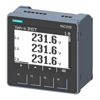
There are 4 dedicated keys F1, F2, F3, F4. use these 4 keys to
enter into confi guration menu / change setting.
Note: The settings should be done by a professional, after
going through this users manual and after having understood
the application situation.
For the confi guration setting mode:
• Use F3 + F4 keys for 3 sec. to enter or exit from the
confi guration menu.
• Use F1 keys to move curser left or right by one digit each
time.
• Use F2 or F3 keys for increasing or decreasing parameters
value.
• Use F2 + F4 key to go back to previous page.
Confi g.
page
Function Range or Selection
Factory
Setting
Password 0000 to 9998 1000
1 Change Password No / Yes No
1.1 New Password 0000 to 9998 1000
2 Network
Selection
3P4W, 3P3W, 1P2W-P1,
1P2W-P2 and 1P2W-P3
3P4W
3 CT Secondary 1A or 5A 5
4 Ct Primary 1A, 5A to 10,000A 5
5 Pt Secondary 100V to 500V 350
6 Pt primary 100V to 500kV 350
7 Slave Id 1 to 255 1
8 Baud Rate 300, 600, 1200, 2400,
4800, 9600 and 19200
(bps)
9600
9 Parity None, Odd, Even None
10 Stop Bit 1 or 2 1
11 Back Light 0 to 7200 sec. 0000
12 Demand interval
method
Sliding / Fixed Sliding
13 Demand interval
duration
1 to 30 15
14 Demand interval
length
1 to 30 min 1
15 Max Page Auto 1 to 22 22
16 Change Page
Sequence
No / Yes No
16.01 Page sequence 1 1 to 22 1
16.02 Page sequence 2 1 to 22 2
16.03 Page sequence 3 1 to 22 3
16.04 Page sequence 4 1 to 22 4
16.05 Page sequence 5 1 to 22 5
16.06 Page sequence 6 1 to 22 6
16.07 Page sequence 7 1 to 22 7
16.08 Page sequence 8 1 to 22 8
16.09 Page sequence 9 1 to 22 9
16.10 Page sequence 10 1 to 22 10
16.11 Page sequence 11 1 to 22 11
16.12 Page sequence 12 1 to 22 12
16.13 Page sequence 13 1 to 22 13
Confi g.
page
Function Range or Selection
Factory
Setting
16.14 Page sequence 14 1 to 22 14
16.15 Page sequence 15 1 to 22 15
16.16 Page sequence 16 1 to 22 16
16.17 Page sequence 17 1 to 22 17
16.18 Page sequence 18 1 to 22 18
16.19 Page sequence 19 1 to 22 19
16.20 Page sequence 20 1 to 22 20
16.21 Page sequence 21 1 to 22 21
16.22 Page sequence 22 1 to 22 22
17 Factory default No / Yes No
18 Reset energy and
MAX demand
No / Yes No
18.1 Password 0001 to 9999 1001
18.01
1)
Reset active
energy
No / Yes No
18.02 Reset reactive
energy
No / Yes No
18.03 Reset apparent
energy
No / Yes No
18.04 Reset MAX No / Yes No
18.05 Reset ON hour No / Yes No
NETWORK SELECTION and WIRING INPUT
Network selection in
confi guration mode
Wiring
3P4W 3P4W, 2P3W
3P3W 3P3W
1P2W (P1/P2/P3) 1P2W (P1/P2/P3)
Note: P1, P2 and P3 are Three Phase.
1) For resetting energy parameters user will be prompted
the password. If correct password is entered, the user
will be able to reset all energy parameters. This password
will be value which will be greater than the confi guration
password by 1.
7
MODBUS REGISTER ADDRESSES LIST
Address Hex Address Parameter
30000 0x00 Voltage V1N
30002 0x02 Voltage V2N
30004 0x04 Voltage V3N
30006 0x06 Average Voltage LN
30008 0x08 Voltage V12
30010 0x0A Voltage V23
30012 0x0C Voltage V31
30014 0x0E Average Voltage LL
30016 0x10 Current I1
30018 0x12 Current I2
30020 0x14 Current I3
30022 0x16 Average Current
30024 0x18 kW1
30026 0x1A kW2
30028 0x1C kW3
30030 0x1E kVA1
30032 0x20 kVA2
30034 0x22 kVA3
30036 0x24 kVAr1
30038 0x26 kVAr2
30040 0x28 kVAr3
30042 0x2A Total KW
30044 0x2C Total KVA
30046 0x2E Total KVAr
30048 0x30 PF1
30050 0x32 PF2
30052 0x34 PF3
30054 0x36 Average PF
30056 0x38 Frequency
30058 0x3A Total net kWh
30060 0x3C Total net kVAh
30062 0x3E Total net kVArh
30064 0x40 kW Max Active Power
30066 0x42 kW Min Active Power
30068 0x44 kVAr Max Reactive Power
30070 0x46 kVAr Min Reactive Power
30072 0x48 kVA Max Apparent Power
30122 0x7A Neutral Current
30124 0x7C THD of 1st Phase Voltage
30126 0x7E THD of 2nd Phase Voltage
30128 0x80 THD of 3rd Phase Voltage
30130 0x82 THD of Voltage V12
30132 0x84 THD of Voltage V23
30134 0x86 THD of Voltage V13
30136 0x88 THD of Current I1
30138 0x8A THD of Current I2
30140 0x8C THD of Current I3
Address Hex Address Parameter
30684 0x2AC Serial no. (Data Structure: Hex)
30692 0x2B4 MAX I1 Demand
30694 0x2B6 MAX I2 Demand
30696 0x2B8 MAX I3 Demand
30698 0x2BA MAX Avg. I Demand
30700 0x2BC Phase Sequence Indication
(0-OK Clockwise, 1-Anticlockwise,
2-Invalid)
30702 0x2BE Existing KW MAX Active Power
30704 0x2C0 Existing KW MIN Active Power
30706 0x2C2 Existing KVAr MAX Reactive Power
30708 0x2C4 Existing KVAr MIN Reactive Power
30710 0x2C6 Existing KVA MAX Apparent Power
30712 0x2C8 Existing MAX I1 Demand
30714 0x2CA Existing MAX I2 Demand
30716 0x2CC Existing MAX I3 Demand
30718 0x2CE Existing MAX Avg. I Demand
30724 0x2D4 DI Status
30726 0x2D6 DI Count
Formula to fi nd address of individual Harmonic
Constant Parameter Meaning
0 Voltage V1N
1 Voltage V2N
2 Voltage V3N
3 Voltage V12
4 Voltage V23
5 Voltage V31
6 Current I1
7 Current I2
8 Current I3
{143 + [(Harmonic no-2) x 2] + 60 x Constant Parameter}
For Example,
To fi nd the 14th Harmonic address of Voltage V31 following
formula can be used:
Formula with the parameter:
{143 + [(Harmonic no-2) x 2] + 60 x C P}
Eg. {143 + [(14-2) x 2 ] + 60 x 5} = 467
So, Check the 14th Harmonic of Voltage V31 at 467 address.
Readable Parameters: [Length (Register): 2; Data Structure: Float]
 Loading...