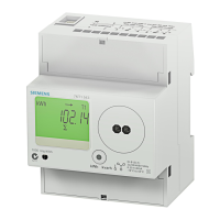
D
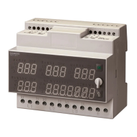
igitale 3-Phasen Energiezähler
Direktanschluß bis 8
0 A
- Wandlerstromanschluß für .
../5 A
bis 10.000/5 A
W
ARNUNG
D
ie Installation muß von einer
Elektrofachkraft oder unter deren
L
eitung und Aufsicht
durchgeführt und geprüft werden.
B
ei Arbeiten am Meßgerät,
Netzspannung abschalten!
Bedienungsanleitung
I
IST007-02
1
)
I
m
D
isplay
d
argestellte
G
rößen
1
a) Energie
• Darstellung nur auf Zählern mit Digitalanzeige bis max. 8 Stellen:
B
zg. Bezeichnung Einheit Symbole ⌺L L1 L2 L3 Tarif
E
1 aufgenommene Wirkenergie MWh/kWh/Wh •••• T1
E
2 abgegebene Wirkenergie MWh/kWh/Wh •••• T1
E3 aufgenommene Blindenergie Mvarh/kvarh/varh •••• T1
E4 abgegebene Blindenergie Mvarh/kvarh/varh •••• T1
E
5 aufgenommene Wirkenergie MWh/kWh/Wh •••• T2
E6 abgegebene Wirkenergie MWh/kWh/Wh •••• T2
E7 aufgenommene Blindenergie Mvarh/kvarh/varh •••• T2
E
8 abgegebene Blindenergie Mvarh/kvarh/varh •••• T2
1b) Leistung
•
Darstellung mittels Balkenanzeige und Anzeige mit 3 Stellen:
B
zg. Leistung Einheit Symbole ⌺L Tarif
P
1 aufgenommene Wirkleistung MW/kW/W • T1
P2 abgegebene Wirkleistung MW/kW/W • T1
P3 aufgenommene Blindleistung Mvar/kvar/var • T1
P4 abgegebene Blindleistung Mvar/kvar/var • T1
P5 aufgenommene Wirkleistung MW/kW/W • T2
P6 abgegebene Wirkleistung MW/kW/W • T2
P7 aufgenommene Blindleistung Mvar/kvar/Var • T2
P8 abgegebene Blindleistung Mvar/kvar/Var • T2
2)
Display-Darstellung (siehe Display Beschreibung)
• Grüne, rückbeleuchtete LCD-Anzeige
• Die verschiedenen Anzeigeebenen werden mit der Steuerungstaste angewählt.
3)
Bedienung
• Die große Anzahl von Meßgrößen macht eine Darstellung der Daten in 2 Anzeigeebenen erforderlich:
A Default
B Energiezählerstände
A) Anzeigeebene Default
• In der Anzeigeebene Default ist die Summe von Wirk- und Blindenergie dargestellt:
- Summe Wirkenergie (E1-E2+E5-E6)
- Summe Blindenergie (E3-E4+E7-E8)
- Softwarestand
- Prüfsumme
• Die verschiedenen Meßgrößen können über ein kurzes Drücken der Steuerungstaste aufgerufen
werden.
• Mit einer 3-stelligen Anzeige wird die momentane Leistung dargestellt. Mittels einer Balkenanzeige
wird der momentane Strom in Schritten von 10% bezogen auf die maximale Belastbarkeit (
Imax
)
angezeigt (Wandleranschluß auf
I
sekundär bezogen). Die Balkenanzeige wird alle 2 Sekunden
aktualisiert.
• Anmerkung: in dieser Anzeigeenebene bezieht sich die Symbolanzeige (Bezug/Abgabe) auf
die aktuelle Leistung und nicht auf den Energieverbrauchswert.
B) Anzeigeebene Energiezählerstände
• In dieser Anzeigeebene werden die Energiewerte E1 bis E8 dargestellt (aus obiger Tabelle).
• Für den Wechsel in die Energiewerte E1-E8 die Steuerungstaste so lange gedrückt halten, bis die rote
LED leuchtet (ca. 4 Sekunden). Die Leistungsanzeigen verschwinden, und auf dem Display werden die
Energiewerte E1-E8 (⌺L) dargestellt.
• Ein kurzer Druck auf die Steuerungstaste ermöglicht die Anzeige dieser Meßwerte in einer Schleife.
• Um zur Anzeigeebene Default zurück zu kommen, die Steuerungstaste ca. 4 Sekunden lang gedrückt
halten oder für eine automatische Umschaltung auf die Ausgangsanzeige ca. 30 Sekunden warten.
• Um alle Energieregister je Phase (Wirk- u. Blindenergie für aufgenommene und abgegebene Energie
für T1 und T2) in einer Schleife zu sehen, Steuerungstaste 2 Sekunden drücken.
• Die Beleuchtung der Anzeige wird nach 40 Sekunden Inaktivität automatisch ausgeschaltet.
3.1) Display-Test Steuerungstaste
• Wenn die Steuerungstaste länger als 10 Sekunden gedrückt wird, wird ein Displaytest aktiviert.
• Dieser Test dauert 30 Sek. Danach erscheint die Anzeigeebene DEFAULT.
3.2) Rückstellung aller Energieregister (nur für MLFB 7KT1 540 und 7KT1 543)
• Wenn die Steuerungstaste länger als 20 Sekunden gedrückt wird erscheint die Schrift “ ”.
• Erst nach nochmaligen Drücken der Steuerungstaste für mindestens 4 Sekunden werden alle
Energieregister auf NULL gestellt.
• Wenn die Steuerungstaste nicht noch einmal gedrückt wird, kehrt die Anzeige ohne Rückstellung nach
4 Sek. zur Ausgangsanzeige zurück.
• Die Rückstellung bei Modellen mit Mid-Beglaubigung ist nicht verfügbar
3.3) Fehleranzeige “Error”
• Wenn im Display die Anzeige “ ” oder “ ” erscheint, liegt eine Fehlfunktion vor
und der Energiezähler muß ausgetauscht werden.
digitale Wirk-/Blindenergie Zähler mit Anzeige der aktuellen Wirk- und Blindleistung
kommunikationsfähig
M
LFB Beschreibung
7
KT1 543 Digitaler 3-Phasen Energiezähler für Direktanschluß 0.25-5 (80) A - 2 Tarife - 2 S0
7KT1 545 Digitaler 3-Phasen Energiezähler für Direktanschluß 0.25-5 (80) A - 2 Tarife - 2 S0
(MiD geeicht)
7
KT1 540 Digitaler 3-Phasen Energiezähler für Wandlerstromanschluß
.
.. /5 A bis 10.000/5 A - 0.05-5 (6) A - 2 Tarife - 2 S0
7KT1 542 Digitaler 3-Phasen Energiezähler für Wandlerstromanschluß
... /5 A bis 10.000/5 A - 0.05-5 (6) A - 2 Tarife - 2 S0
(MiD geeicht)
1
)
Q
uantities
d
isplayed
1
a) Energy
• They are displayed on the main 8 digits counter:
R
ef. Energy Unit Symbol ⌺L L1 L2 L3 Tariff
E1 Active Absorbed MWh/kWh/Wh •••• T1
E
2 Active Supplied MWh/kWh/Wh •••• T1
E3 Reactive Absorbed Mvarh/kvarh/varh •••• T1
E4 Reactive Supplied Mvarh/kvarh/varh •••• T1
E
5 Active Absorbed MWh/kWh/Wh •••• T2
E6 Active Supplied MWh/kWh/Wh •••• T2
E7 Reactive Absorbed Mvarh/kvarh/varh •••• T2
E
8 Reactive Supplied Mvarh/kvarh/varh •••• T2
1
b) Power
• Powers are displayed on the bar indicator and also on the 3 digits secondary counter:
R
ef. Power Unit Symbol ⌺L Tariff
P1 Active Absorbed MW/kW/W • T1
P
2 Active Supplied MW/kW/W • T1
P3 Reactive Inductive Mvar/kvar/var • T1
P4 Reactive Capacitive Mvar/kvar/var • T1
P5 Active Absorbed MW/kW/W • T2
P6 Active Supplied MW/kW/W • T2
P7 Reactive Inductive Mvar/kvar/Var • T2
P8 Reactive Capacitive Mvar/kvar/Var • T2
2)
Display View (see quantities displayed)
• A green backlighted LCD display.
• With the front push button all register will appear.
3)
The user information
• The wide range of measurement available needs the adoption of groups. All the data
are currently displayed using 2 different groups:
A default vision group
B all energy counters
A) The default vision group
• The default group lists the energy balances, as unsigned values:
- Active energy balance (E1-E2+E5-E6)
- Reactive energy balance (E3-E4+E7-E8)
- Software version
- Checksum n°
• A short pressure of the command button allow to go through the measurements (
active/reactive)
.
• In the default group there is also a counter that shows the instant power. Beside this counter, a bar
indicator shows the current percentage, in step of 10%, respect to the full scale
(CT version related to
I
secondary). The bar indicator is updated every 2 seconds.
• Note: in this group the symbol indicator refers to the instant power and not to the
energy balance
B) All energy counters
• This group is dedicated to store the energy values E1-E8 as described in the previous table.
• Press the “command button” for 4 seconds. After this time, the red led on the front panel lights on.
The power indicators disappear and the display is completely dedicated to show the energy
values E1-E8 (⌺L).
• A short pressure of the “command button” allow a loop vision of these values.
• To go back to the default visualization press the command button for 4 sec., or without any command
it will happen automatically after 30 sec.
• Press “command button” for 2 sec. in order to scroll all the Energy register available for each phase
L1, L2, L3 (active, reactive, absorbed and supplied energy T1-T2)
• The backlight of the display returns automatically switched off (after 40 sec. of inactivity).
3.1) Display test
• Pressure of the “command button” for more then 10 sec. causes the test of all the display segments.
• The test will last for a fixed time of 30 sec. then it will go back to the default visualization.
3.2) Zeroing all registers (only 7KT1 540 - 7KT1 543 models)
• A pressure of 20 sec. of the “command button” allows to enter in the zeroing menu and on the display
appears “ ”.
• The button must be released. To do the reset press it again for 4 sec., afterwards it will go back to the
default visualization with all registers reset.
• After 4 sec. from the button release if the “command reset” is not done, it will go back to the default
visualization without the reset.
3.3) Error condition
• When the display shows the message “ ” or “ ”, the meter has got a malfunction
and must be replaced.
three-phase digital active and reactive energy-meter with measurement
of active and reactive instantaneous power, set up for communication
C
ode Description
7KT1 543 three-phase digital with direct connection 0.25-5 (80) A - 2 tariff - 2 S0
7
KT1 545 three-phase digital with direct connection 0.25-5 (80) A - 2 tariff - 2 S0 (MID calibrated)
7
KT1 540 three-phase digital with connection
by CT .../5 A, up to 10.000/5 A - 0.05-5 (6) A - 2 tariff - 2 S0
7KT1 542 three-phase digital with connection
b
y CT .../5 A, up to 10.000/5 A - 0.05-5 (6) A - 2 tariff - 2 S0 (MID calibrated)
W
ARNING
I
nstallation must be carried out
and inspected by a specialist or
u
nder his supervision.
W
hen working on the instrument,
switch off the mains voltage!
Operating instructions
ENGLISH
T
hree-phase Digital Energy meters
Direct connection 8
0 A
- Connection through C
T .../5 A
till 10.000/5 A
S
tand 13-09-2010
DEUTSCH 2
51428.41.17 “03”