Do you have a question about the Siemens SMART 7KT0311 and is the answer not in the manual?
Describes the manual's intended audience and scope for the SMART 7KT meter.
Outlines prerequisites for understanding the manual, focusing on electrical engineering.
Lists items included in the product packaging, such as the meter, clamps, and gasket.
Covers hazardous voltage, qualified personnel, environmental considerations, and isolation during testing.
Details measurement procedures, supply voltage, protection class, and suitability for installation.
Lists product functions, display design, operation features, and accuracy standards.
Specifies digital I/O, measuring input ranges, and electrical connection types for the meter.
Covers physical dimensions, mounting, weight, and operating environmental limits.
Lists measurable variables on display/communication and relevant IEC standards.
Confirms conformity to IEC standards and IPC electronics assembly standards.
Provides step-by-step diagrams for preparing the panel cutout and mounting the meter.
Offers best practices for safe installation, circuit breaker use, and wiring connections.
Illustrates the step-by-step process for safely removing the meter from its panel mount.
Presents a general diagram showing power and communication connections for the meter.
Shows detailed circuit diagrams for 3-phase 4-wire and 2-phase 3-wire configurations.
Provides circuit diagrams for 3-phase 4-wire, 3-phase 3-wire, and 1-phase 2-wire systems.
Explains the use of F1-F4 keys for reading parameters and navigating configuration menus.
Details how to enter and switch between automatic and manual display modes.
Describes the procedure for entering configuration mode using the default password.
Lists configuration parameters, their pages, functions, ranges, and factory settings.
Lists parameters displayed in manual mode for 3P4W network selection.
Lists parameters displayed in manual mode for 3P3W network selection.
Lists parameters displayed in manual mode for 1P2W-P1 network selection.
Lists parameters displayed in manual mode for 1P2W-P2 network selection.
Lists parameters displayed in manual mode for 1P2W-P3 network selection.
Lists parameters displayed in auto mode with DG for 3P4W network selection.
Lists parameters displayed in auto mode with DG for 3P3W network selection.
Lists parameters displayed in auto mode with DG for 1P2W-P1 network selection.
Lists parameters displayed in auto mode with DG for 1P2W-P2 network selection.
Lists parameters displayed in auto mode with DG for 1P2W-P3 network selection.
Lists parameters in manual mode without DG for 3P4W network selection.
Lists energy parameters in manual mode without DG for 3P4W network selection.
Lists parameters in manual mode without DG for 3P3W network selection.
Lists parameters in manual mode without DG for 1P2W-P1 network selection.
Lists parameters in manual mode without DG for 1P2W-P2 network selection.
Lists parameters in manual mode without DG for 1P2W-P3 network selection.
Lists parameters in auto mode without DG for 3P4W network selection.
Lists parameters in auto mode without DG for 3P3W network selection.
Lists parameters in auto mode without DG for 1P2W-P1 network selection.
Lists parameters in auto mode without DG for 1P2W-P2 network selection.
Lists parameters in auto mode without DG for 1P2W-P3 network selection.
Outlines the Modbus RTU protocol and integrated RS485 interface specifications.
Lists communication settings like address, transmission mode, speed, and parity.
Provides a list of readable float parameters and their Modbus addresses.
Continues the list of readable float parameters and their Modbus addresses.
Continues the list of readable float parameters and their Modbus addresses.
Continues the list of readable float parameters and their Modbus addresses.
Lists readable/writable integer parameters and their Modbus addresses.
Continues the list of readable/writable integer parameters and their Modbus addresses.
Provides instructions for regularly cleaning the equipment to avoid blockages.
Advises on proper disposal or recycling of the module according to local laws.
| Product brand name | Siemens |
|---|---|
| Product designation | SMART 7KT0311 |
| Design of display | LCD |
| Operating voltage | 230 V AC |
| Supply voltage frequency | 50/60 Hz |
| Measuring category | CAT III |
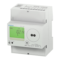
| Mounting type | DIN rail |
| Width | 72 mm |
| Height | 90 mm |
| Depth | 64 mm |
| Device Type | Energy meter |
| Model | 7KT0311 |
| Manufacturer | Siemens |
| Category | Measuring Instruments |
| Accuracy Class | Class 1 |
| Voltage Rating | 230 V |
| Current Rating | 5 A |
| Frequency | 50/60 Hz |
| Protection Class | IP20 |
| Type of connection technology | Screw terminal |
| Operating Temperature | -10 to +55 °C |
| Storage Temperature | -25 to +70 °C |