7SG11 Argus 8 Description of Operation
2 Hardware Description
2.1 General
All of the Argus range of relays share common hardware components and modules. The design for the
mechanical arrangement of the relays has been carefully chosen to provide a high level of EMI
screening using multi-layer PCB’s with ground planes, RFI suppression components and earthed
metal screens. The internal arrangement has been divided into noisy and quiet areas in order to
improve noise immunity and reduce RFI emissions. The only direct connection from the quiet
components to the external environment is via the optical serial communications interface, which is
immune to radiated or conducted interference.
2.2 Analogue Inputs
The input stage of an Argus 8 relay measures either two or three voltage quantities depending upon the particular
variant. Over the range of 5 Vrms to 200 Vrms it maintains accuracy within ±1% (or 0.25V) over the declared
frequency performance range. The wide measuring range of the input stage allows for either phase-phase or
phase-neutral connections e.g. 110Vrms or 63.5Vrms nominal voltages.
Note : on relay variants which have a 2Ph-Ph connection setting, the 3
rd
phase voltage can be calculated from the
two known phases if the external connection is connected phase-phase.
In order to ensure high accuracy voltage, frequency and sequence component calculations the voltage
signals are sampled at 32 samples per cycle for both 50Hz and 60Hz system frequencies. The high
sampling rate provides high accuracy and quality waveform storage records, which are stored at a rate
of 16 samples per cycle.
2.3 Output Relays
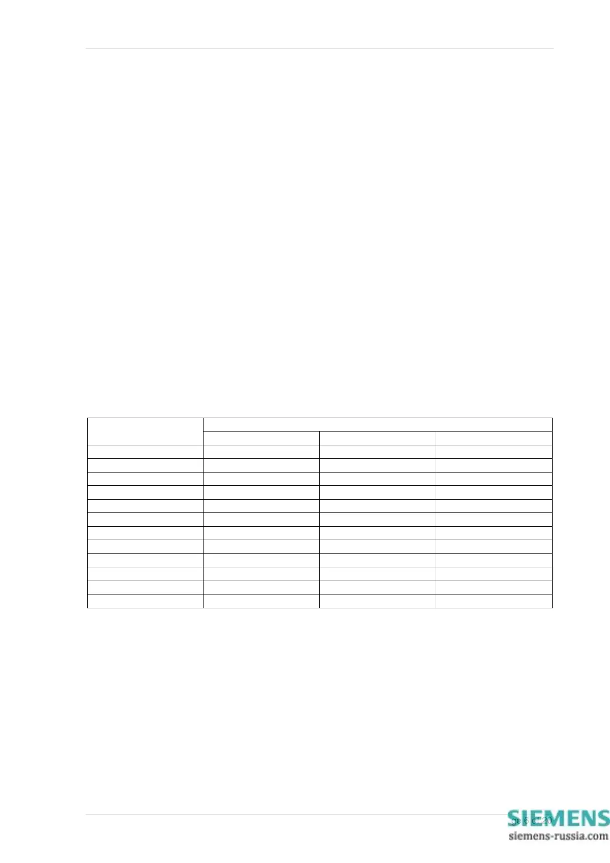
Argus 8 relays have a variety of output contact types available depending upon the case size and expansion card
option. The full range is given in Table 3.
Output Relays Available
Catalogue Number
C/O Contact N/O Contact N/C Contact
AG8 101-103 1 5 1
AG8 201-203 1 5 1
AG8 301-303 1 5 1
AG8 104-106 3 4 -
AG8 204-206 3 4 -
AG8 304-306 3 4 -
AG8 107-109 3 4 -
AG8 207-209 3 4 -
AG8 307-309 3 4 -
AG8 110-112 3 8 -
AG8 210-212 3 8 -
AG8 310-312 3 8 -
Table 3 - Output Relay Types
All output relays are fully user configurable and can be programmed to operate from any or all of the protection
functions. In addition, a watchdog feature within the relay can be mapped to any of the output relays. A
changeover or normally-closed contact is generally required for this.
All output relays are of the same design and therefore each is capable of handling direct circuit breaker-tripping
duty.
Output relays can be set to remain energised for a minimum time of between 100-500msec. If required, however,
outputs can be programmed to operate as latching relays. These latched outputs can be reset by either pressing
the TEST/RESET button, by energising a status input or by sending an appropriate communications command.
A trip test feature is provided to exercise the output contacts.
For a list of terminal numbers and their usage see Tables 4 and 5 at the back of this section.
©2011 Siemens Protection Devices Limited Chapter 1 Page 6 of 20