7SG11 Argus 8 Relay Settings
©2011 Siemens Protection Devices Limited Chapter 3 Page 9 of 10
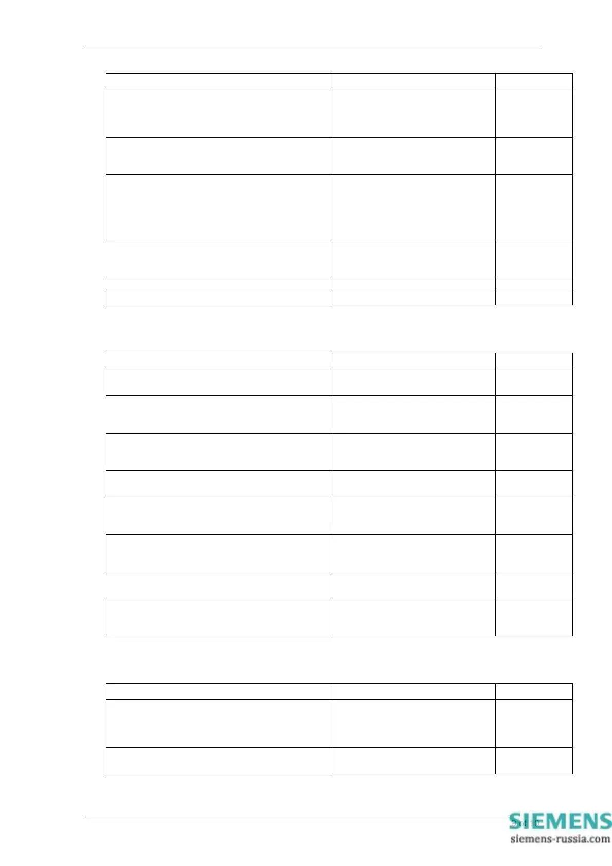
SETTING RANGE DEFAULT
Gn Clock Sync.
sets the status input(s) which, on energisation, will
synchronise the real time clock to the nearest
second or minute
S1..Sn None
Gn Reset Outputs
sets the status input(s) which, on energisation, will
reset the Trip LED and any latched output relays
S1..Sn None
Gn Status 1 P/U Delay
sets the delay period to be applied to the pick-up of
Status Input 1
0 – 2.00 sec step 10ms
2.10 – 20.00 sec step 100ms
21 – 300 sec step 1 sec
360 – 3600 sec step 60 sec
3900 – 14400 sec step 300 sec
0.02sec
Gn Status 1 D/O Delay
sets the delay period to be applied to the drop-off of
Status Input 1
As above 0.00sec
Gn Status n P/U Delay
As Status 1 0.02sec
Gn Status n D/O Delay
As Status 1 0.00sec
10 Comms Interface Menu
SETTING RANGE DEFAULT
Comms Protocol
Sets the communications protocol
IEC60870-5-103,
MODBUS-RTU
IEC60870-5-
103
Class 2 Update Period
Sets the IEC60870 Class 2 measurand update
period
INST, 1 – 60 sec 15 sec
IEC Class 2 Scaling
Sets the IEC60870 Class 2 measurand scaling
factor
1.2x, 2.4x 1.2x
Comms Baud Rate
sets the required communications Baud Rate
75, 110, 150, 300, 600, 1200, 2400,
4800, 9600, 19200
19200
Comms Parity
selects whether a parity check is transmitted with
the comms data
NONE, EVEN EVEN
Relay Address
sets the required address of a particular relay within
a network
0 – 254 0
Line Idle
sets the required communications line idle sense
LIGHT ON, LIGHT OFF LIGHT OFF
Data Echo
enables Data Echo which is necessary for use with
relays connected in a ring
OFF / ON OFF
11 Data Storage Menu
SETTING RANGE DEFAULT
Gn Fault Trigger
sets the output relay(s) which are connected as trip
outputs for the purpose of giving trip information and
storing fault records
RL1..RLn None
Gn Waveform Trig
selects which functions trigger a waveform record
STA, V, F, NPS, NVD STA+V+NPS+
NVD+F