5-47
System Manual
C79000-G8576-C199-07
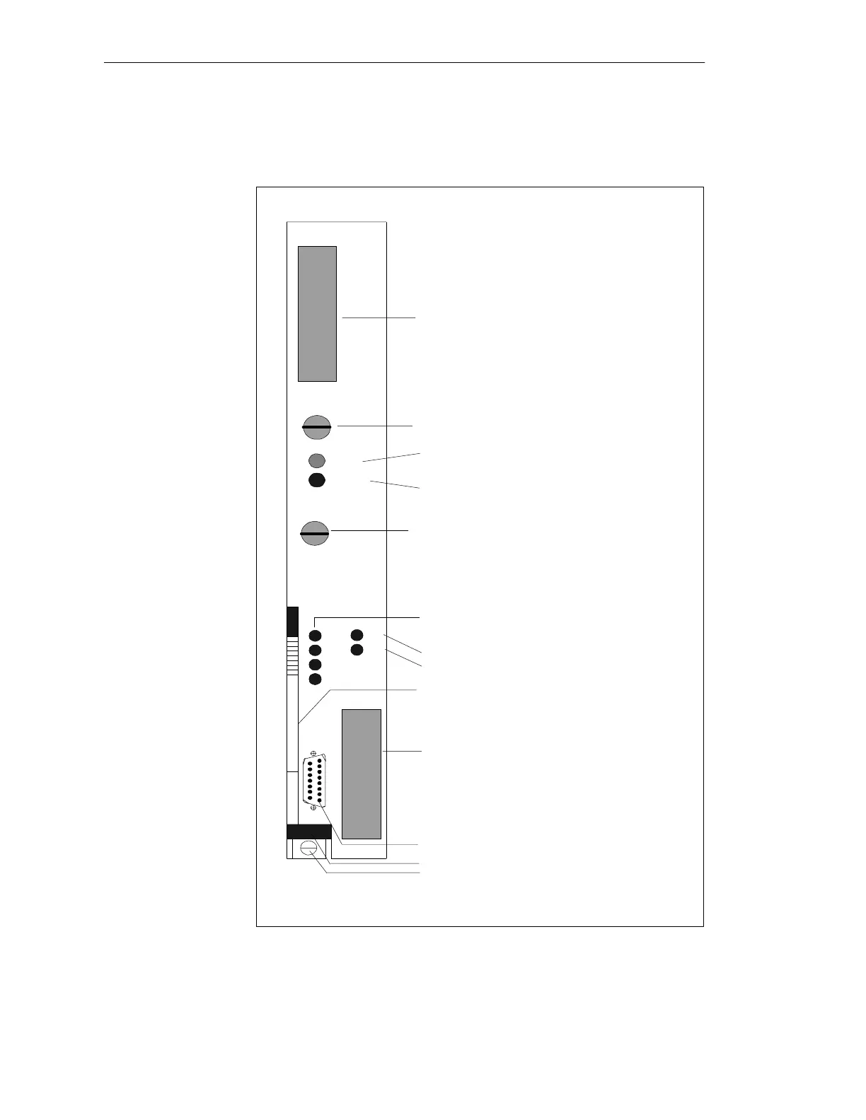
The controls and indicators are arranged on the front plate of the CPU
module:
SIEMENS
Receptacle for
User Memory Submodule
Mode Switch
LED (green)
LED (red)
Momentary-Contact Mode Switch
Fault Indicator LEDs (red)
PG Interface, 15-Pin
Interface SI 1
Release Lever
Locking Pin
Interface Fault Indicator LEDs (red)
Interface 1
Interface 2
RUN
STOP
RUN
STOP
RÜCKSETZEN
RESET
URLÖSCHEN
OVERALL RESET
SI1
SI2
QVZ
ADF
ZYK
BASP
Order Number and Version
Receptacle for Interface Submodule
Interface SI 2
SI2
SI1
6ES5928-3UB12
CPU 928B
Figure 5-6 Front Plate of the CPU 928B
Controls and
Indicators
CPUs, Memor
Cards, Memor
Submodules, Interface Submodules