19/30
Smart Infrastructure CC1N7544en
21.05.2021
Technical Data (cont´d)
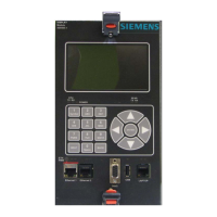
Display, BCI For installation under the burner hood or
in the control panel
Load controller analog X64 (24 mA)
External lockout reset button
Fuel valve (V1 / V2 / V3)
¹) Do not run the cable together with other cables. If not observed, hum voltage might
cause electromagnetic interference
²) Shorter cable length due to closed control loop
EN 60730-1:2016
Type of shutdown or interruption of each circuit
Shutdown with microswitch
Mode of operation
The cross-sectional areas of the mains power lines (L, N, and PE) and, if required, the
safety loop (safety limit thermostat, water shortage, etc.) must be sized for rated
currents according to the selected external primary fuse. The cross-sectional areas of
the other cables must be sized in accordance with the internal unit fuse (max. 6.3 AT).
Min. cross-sectional area 0.75 mm² (single- or multi-core as per
Cable insulation must meet the relevant temperature requirements and environmental
conditions.
Fuses (F1) used inside the
The fixed connected actuator cables must not be extended.
Signal cable Color white
Unshielded
Conductor 4 x 0.141 mm²
Cable length
- AGV50.100
1 m
Location Under the burner hood (extra measures
required for SK
EN 60730-1:2016)
Connections of
AGV50 signal cable
AZL2 BCI

 Loading...

