2
Siemens AG 03.2011
Technische Daten
Technical data
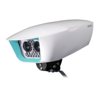
Modell CCAW1417-LPO Model CCAW1417-LPO
Spannungsversorgung 12 V DC / 24 V AC, 0,75 A, 50 Hz Power supply 12 V DC / 24 V AC, 0.75 A, 50 Hz
Heizung 24 V AC, 0,84 A, 50 Hz Heating 24 V AC, 0.84 A, 50 Hz
Auflösung 560 TV-Zeilen (Farbe), 600 TV-Zeilen (S/W) Resolution 560 TV lines (colour), 600 TV lines (B/W)
Mindestbeleuchtung 0,5 Lux (Farbe) bei F1,6 (AGC On,
50 IRE ), 0,05 Lux (S/W), 0,001 Lux (slow
shutter)
Min. illumination 0.5 lux (colour) at F1.6 (AGC on, 50 IRE
video output), 0.05 lux (B/W), 0.001 lux
(slow shutter)
-10 bis +50°C ohne Heizung -10 to +50°C without heater Betriebstemperatur
-30 bis +50°C mit Heizung
Operating temperature
-30
to +50°C with heater
Lagertemperatur -20 bis +60°C
Storage temperature -20 to +60°C
Rel. Luftfeuchtigkeit 0 – 96% (nicht kondensierend) Relative humidity 0 – 96% (non-condensing)
Schutzart IP66 Protection type IP66
Bestellangaben
Details for ordering
Typ CCAW1417-LPO Type CCAW1417-LPO
Bestellnummer S54561-C35-A1 Order No. S54561-C35-A1
Bezeichnung ¼ Zoll Kamera T/N WD AF Designation ¼ inch camera D/N WD AF
Gewicht 1,5 kg Weight 1.5 kg
Installation
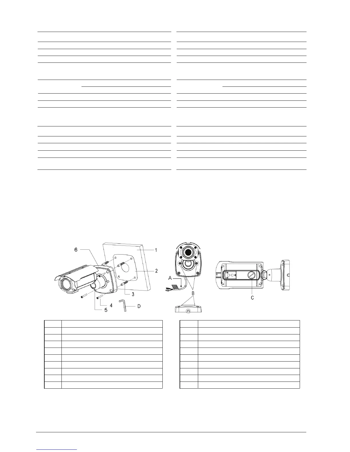
Schritt 1: Montage der Kamera
1. Bohren Sie mit der Bohrschablone (oder der Befestigungsplatte)
die erforderlichen Befestigungslöcher.
2. Setzen Sie die Dübel ein.
3. Entfernen Sie bei Bedarf den vorgestanzten Verschluss für die
Kabeleinführung.
4. Schließen Sie das BNC- und die Kommunikationskabel an.
5. Drehen Sie die Schrauben ein (T-20).
6. Richten Sie die Kamera aus und ziehen Sie die Madenschraube (5)
und die Torx-Schraube (B) fest, um die Kamera zu fixieren.
Installation
Step 1: Mounting the camera
1. Drill the mounting location, using the drill template (or the bottom
of the mount base) as a template.
2. Insert the plastic anchors into the hole which has just drilled.
3. If necessary remove the conduit knockout punched for the cable
entry.
4.Connect BNC cable and communication lines.
5.Screw up the mount screws (T-20).
6. Adjust the camera suitably and fasten both the socket set screw
(5) and torx lock screw (B) to fix the camera.
Fig. 2
1 Wand
2 Bohrschablone
3 Kunststoffdübel (4x, Ø 8 mm)
4 Schrauben (T-20, Größe 6x35 mm, 4x)
5 Madenschraube M5 x 5 mm
6 Befestigungsplatte
A Kabel
B Torx-Schraube (T-20)
C DIP-Schalter
D Sechskantschlüssel
Schritt 2: Anschließen des Videosignals
Wählen Sie eine der folgenden Optionen:
z Verbinden Sie den BNC-Stecker der Kamera über ein
Koaxialkabel mit dem Monitor.
1 Wall
2 Drill template
3 Plastic anchors (4x, Ø 8 mm)
4 Mounting screws (T-20, size 6x35 mm, 4x)
5 Set screw M5 x 5 mm
6 Mounting base
A Cable
B Torx lock screw (T-20)
C DIP switch
D Hexagon wrench
Step 2: Connecting the video signal
Select one of the following options:
z Connect the pre-assembled BNC connector to the monitor using a
coax cable.
 Loading...