3
Siemens AG 03.2011
z Verbinden Sie die Punkte TP-A/TP-B mit dem UTP-Kabel (Fig 3).
Gelb TP-A(+)
Grün/Weiß TP-B(-)
Schritt 3: Synchronisation
Bei dieser Kamera ist der LL- und der INT-Modus wählbar. Ab Werk
ist der INT-Modus eingestellt (siehe OSD-Menü).
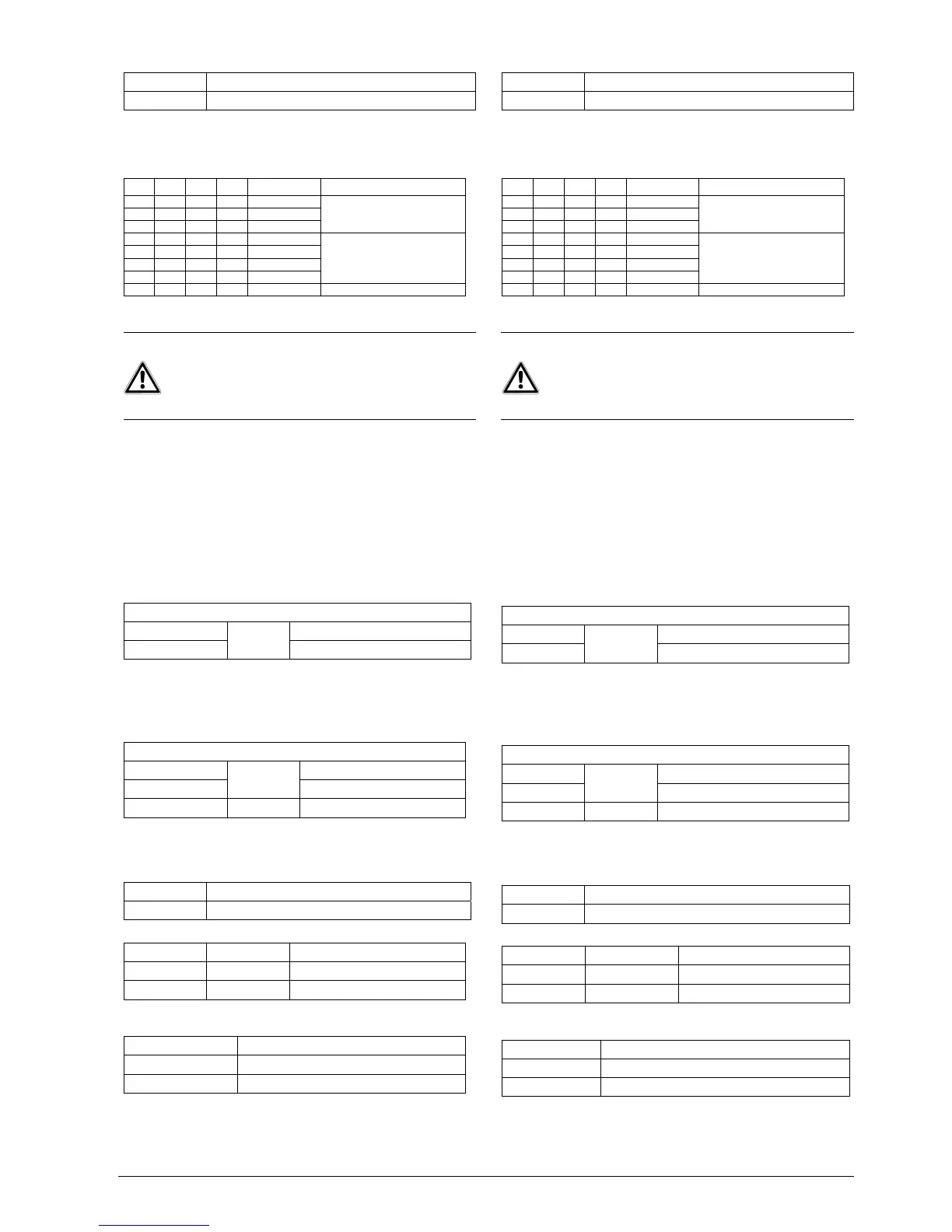
Schritt 4: DIP-Schalter
S1 S2 S3 S4 Beschreibung
Off Off 2,0 Vss
On Off 2,6 Vss
On On 3,2 Vss
Ausgangsspannung ohne
Anhebung
Off Off 0 dB
Off On 6 dB
On Off 6 dB
On On 12 dB
Frequenzabhängige Anhebung
bei 5 MHz
On Off Off Off Werkseinstellung
Schritt 5: Anschließen der Stromversorgung
Schließen Sie die Spannungsversorgung an das Kabel an.
z Connect the terminals TP-A/TP-B to the UTP cable (Fig. 3).
Yellow TP-A(+)
Green/White TP-B(-)
Step 3: Synchronization
LL and INT mode are available for this camera. The factory default
is INT mode (see OSD menu).
Step 4: DIP switch
S1 S2 S3 S4 Beschreibung
Off Off 2,0 Vss
On Off 2,6 Vss
On On 3,2 Vss
Output voltage without
accentuation
Off Off 0 dB
Off On 6 dB
On Off 6 dB
On On 12 dB
Frequency dependent
accentuation at 5 MHz
On Off Off Off Condition on delivery
Step 5: Connecting the power supply
Connect the power supply cable to the power connectors.
VORSICHT
Gefahr von Kameraschäden und Fehlfunktionen
Bei Anschlussfehlern der Gleichstromversorgung kann es
zu Kameraschäden und Fehlfunktionen kommen.
z Achten Sie auf die korrekte Polarität.
CAUTION
Risk of malfunction and damage to the camera
If using a DC supply, incorrect connection may cause
malfunction and/or damage to the camera.
z Make sure the polarity is correct.
Wählen Sie eine der folgenden Optionen:
z 12 V DC:
Schließen Sie 12 V (-) am weißen, 12 V (+) am roten Kabel an.
z 24 V AC:
Schließen Sie 24 V (~) am weißen und roten Kabel an.
z 24 V AC – Heizung (bis -30°C):
Schließen Sie 24 V (~) am rosa und braunen Kabel an.
Schritt 6: Zusätzliche Anschlussmöglichkeiten
Steuereingang für Tag-/ Nachtumschaltung
Mit dem Steuereingang kann die Kamera von Tag- auf Nacht-
Betrieb mit/ohne Alarmkennung umgeschaltet werden.
Positionen des externen Sensorschalters (Fig. 3)
Grau Offen: Farbe / Alarm Aus
Schwarz (GND)
Externer
Eingang
Geschlossen: S/W / Alarm Ein
Um die Sensoreingänge zu aktivieren, wählen Sie im
Funktionsmenü "B/W" oder "ALARM" den Modus "EXT".
Steuerausgang/ Tag-/Nachtumschaltung oder Alarmerkennung
Mit dem Steuerausgang können die Betriebszustände Farbe/ S/W
oder Alarmerkennung angezeigt werden.
Potential des externen Ausgangs (Fig. 3)
Weiß/Schwarz Tag-Modus: 0-V-Ausgang
Schwarz (GND)
Externer
Ausgang
Nacht-Modus: 5-V-Ausgang
Violett MD-Ausg. MD/FD Aus: 0 V, Ein: 3,3 V
Anschließen der RS-485 Datenschnittstelle
Die Kamera kann mittels RS-485 halbduplex dezentral durch ein
externes Gerät gesteuert werden. Verbinden Sie die Leitungen Rx+,
Rx- mit Tx+ und Tx- des RS-485 Steuerungssystems (Fig. 3).
Grün RS-485(+)
Blau RS-485(-)
Anschließen der Fernbedienung
Kamera Fernbedienung
Schwarz GND Schwarz
Blau/Weiß A/D-Key Weiß
Das Kabel der Fernbedienung darf nicht verlängert werden!
Anschließen der RS-232 Schnittstelle für PC-Parametrierung
Orange/Schwarz RS-232 TxD
Orange RS-232 RxD
Schwarz GND
Select one of the following options:
z 12 V DC:
Connect 12 V (-) to the white, 12 V (+) to the red cable.
z 24 V AC:
Connect 24 V (~) to the white and red cable.
z 24 V AC – Heater (up to -30°C):
Connect 24 V (~) to he pink and brown cable.
Step 6: Further connection possibilities
Control input for switching between day/night mode
This control input can be used to switch between day/night mode
with/without alarm detect.
Positions of the external sensor switch (Fig. 3)
Grey Open: COLOR / ALARM OFF
Black (GND)
EXT-In
Closed: B/W / ALARAM ON
Select "EXT" in the "B/W" or “ALARM” functions menu to activate
the sensor inputs.
Control output for day/night mode or alarm detect
This control output can be used to show the camera status of
Colour/ B/W mode with/without alarm detect.
Potential of the external output (Fig. 3)
White/Black Day: 0 V output
Black (GND)
EXT-Out
Night: 5 V output
Violet MD-Out MD/FD NONE: 0 V, ON: 3.3 V
Connecting the RS-485 data interface
The camera can be controlled remotely by an external control
system using RS-485 semi-duplex. Connect marked Rx+, Rx- to
Tx+ and Tx- of the RS-485 control system (Fig. 3).
Green RS-485(+)
Blue RS-485(-)
Connecting the remote control
Camera Remote control
Black GND Black
Blue/White A/D key White
Do not extend the connecting cable of the remote control!
Connecting the RS-232 interface for configuration via PC
Orange/Black RS-232 TxD
Orange RS-232 RxD
Black GND
 Loading...