LEDs and connectors
3.3 Electrical connectors
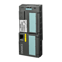
CP 1243-1 PCC
20 Operating Instructions, 02/2015, C79000-G8976-C384-01
Firmware being loaded.
The "DIAG" LED flashes alternating
red and green.
Firmware was successfully loaded.
Errors:
• Error loading firmware
• Internal error of the CP
remedy: Power OFF → ON
Electrical connectors
3.3.1
Power supply
Power supply
The CM is supplied with power from the backplane bus. It does not require a separate power
supply.
Ethernet interface X1P1
Ethernet interface
The Ethernet connector is located behind the lower hinged cover of the module. The
interface is an RJ-45 jack according to IEEE 802.3.
The pin assignment and other data relating to the Ethernet interface can be found in the
section Technical specifications (Page 61).

 Loading...