CPUs
1-32
PLC S7-300, CPU Specifications CPU 312 IFM to CPU 318-2 DP
A5E00111190-01
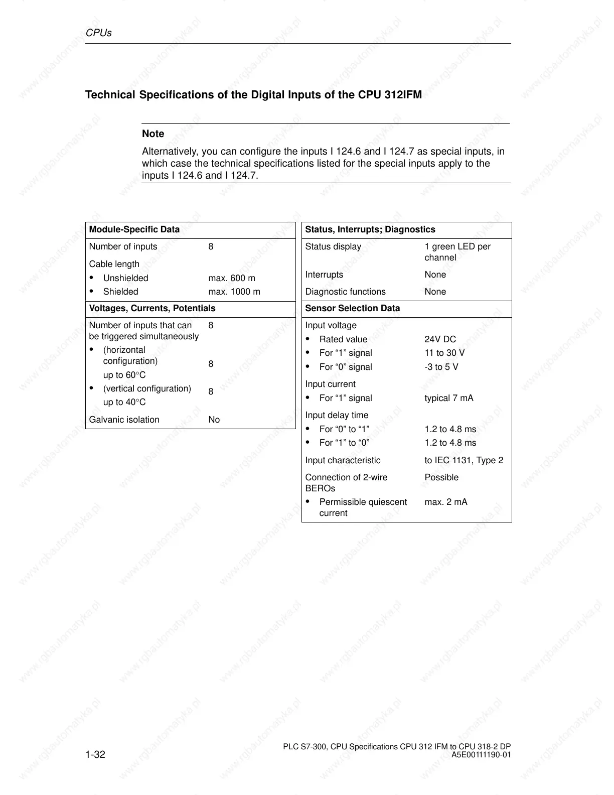
Technical Specifications of the Digital Inputs of the CPU 312IFM
Note
Alternatively, you can configure the inputs I 124.6 and I 124.7 as special inputs, in
which case the technical specifications listed for the special inputs apply to the
inputs I 124.6 and I 124.7.
Module-Specific Data
Number of inputs 8
Cable length
Unshielded
Shielded
max. 600 m
max. 1000 m
Voltages, Currents, Potentials
Number of inputs that can
be triggered simultaneously
(horizontal
configuration)
up to 60°C
(vertical configuration)
up to 40°C
8
8
8
Galvanic isolation No
Status, Interrupts; Diagnostics
Status display 1 green LED per
channel
Interrupts None
Diagnostic functions None
Sensor Selection Data
Input voltage
Rated value
For “1” signal
For “0” signal
24V DC
11 to 30 V
-3 to 5 V
Input current
For “1” signal typical 7 mA
Input delay time
For “0” to “1”
For “1” to “0”
1.2 to 4.8 ms
1.2 to 4.8 ms
Input characteristic to IEC 1131, Type 2
Connection of 2-wire
BEROs
Permissible quiescent
current
Possible
max. 2 mA
 Loading...

