CPUs
1-33
PLC S7-300, CPU Specifications CPU 312 IFM to CPU 318-2 DP
A5E00111190-01
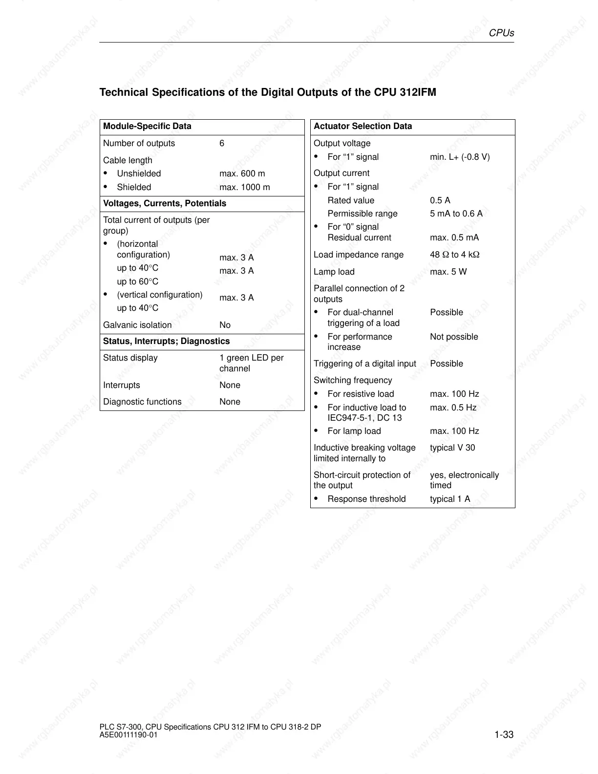
Technical Specifications of the Digital Outputs of the CPU 312IFM
Module-Specific Data
Number of outputs 6
Cable length
Unshielded
Shielded
max. 600 m
max. 1000 m
Voltages, Currents, Potentials
Total current of outputs (per
group)
(horizontal
configuration)
up to 40°C
up to 60°C
(vertical configuration)
up to 40°C
max. 3 A
max. 3 A
max. 3 A
Galvanic isolation No
Status, Interrupts; Diagnostics
Status display 1 green LED per
channel
Interrupts None
Diagnostic functions None
Actuator Selection Data
Output voltage
For “1” signal min. L+ (-0.8 V)
Output current
For “1” signal
Rated value
Permissible range
For “0” signal
Residual current
0.5 A
5 mA to 0.6 A
max. 0.5 mA
Load impedance range 48 to 4 k
Lamp load max. 5 W
Parallel connection of 2
outputs
For dual-channel
triggering of a load
For performance
increase
Possible
Not possible
Triggering of a digital input Possible
Switching frequency
For resistive load
For inductive load to
IEC947-5-1, DC 13
For lamp load
max. 100 Hz
max. 0.5 Hz
max. 100 Hz
Inductive breaking voltage
limited internally to
typical V 30
Short-circuit protection of
the output
Response threshold
yes, electronically
timed
typical 1 A
 Loading...

