CPUs
1-53
PLC S7-300, CPU Specifications CPU 312 IFM to CPU 318-2 DP
A5E00111190-01
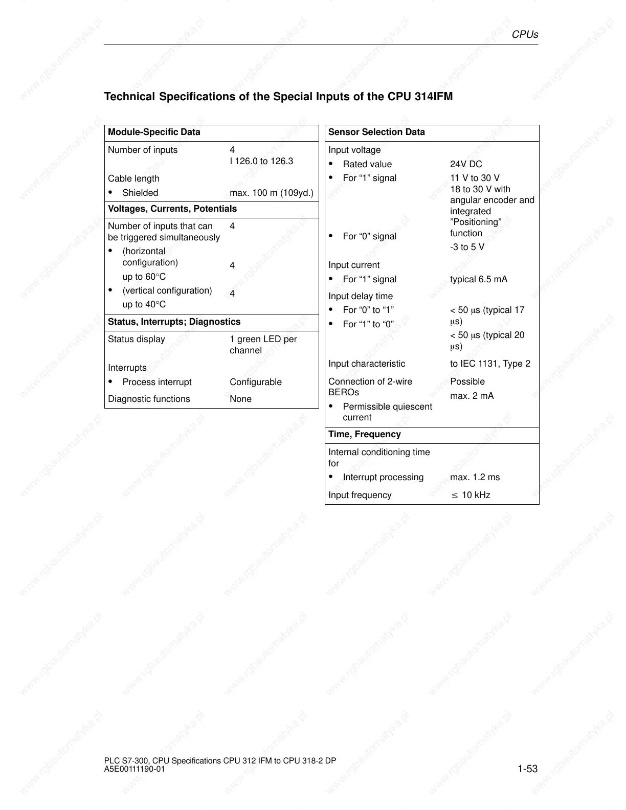
Technical Specifications of the Special Inputs of the CPU 314IFM
Module-Specific Data
Number of inputs 4
I 126.0 to 126.3
Cable length
Shielded max. 100 m (109yd.)
Voltages, Currents, Potentials
Number of inputs that can
be triggered simultaneously
(horizontal
configuration)
up to 60°C
(vertical configuration)
up to 40°C
4
4
4
Status, Interrupts; Diagnostics
Status display 1 green LED per
channel
Interrupts
Process interrupt Configurable
Diagnostic functions None
Sensor Selection Data
Input voltage
Rated value
For “1” signal
For “0” signal
24V DC
11 V to 30 V
18 to 30 V with
angular encoder and
integrated
”Positioning”
function
-3 to 5 V
Input current
For “1” signal typical 6.5 mA
Input delay time
For “0” to “1”
For “1” to “0”
< 50 s (typical 17
s)
< 50 s (typical 20
s)
Input characteristic to IEC 1131, Type 2
Connection of 2-wire
BEROs
Permissible quiescent
current
Possible
max. 2 mA
Time, Frequency
Internal conditioning time
for
Interrupt processing
max. 1.2 ms
Input frequency 10 kHz
 Loading...

