EasyManua.ls Logo

Siemens DLC User Manual

Siemens DLC
10 pages
To Next Page IconTo Next Page
Page #1 background imageLoading...
Page #1 background image
Siemens Siemens
Siemens Siemens
Siemens
IndustryIndustry
IndustryIndustry
Industry
,,
,,
,
Inc. Inc.
Inc. Inc.
Inc.
Building Building
Building Building
Building
TT
TT
T
ecec
ecec
ec
hnologies Dihnologies Di
hnologies Di
visionvision
visionvision
vision
P/N 315-033090-17
Device Loop Card
Installation Instructions
Model DLC
INTRODUCTION The Model DLC Device Loop Card from Siemens Industry,
Inc., is the interface for connection of FireFinder-XLS/Desigo
Fire Safety Modular/Cerberus PRO Modular smoke detec-
tors, Multi-Criteria detectors including Carbon Monoxide,
manual stations, monitor devices, and control devices to the
FireFinder-XLS/Desigo Fire Safety Modular/Cerberus PRO
Modular System. The DLC uses one network address on the
system. The application program that is loaded into the on-
board microprocessor controls the DLC operation.
The DLC contains 12 LEDs for diagnosis of problems.
Ground fault detection is provided by the loop.
All field devices connected to the DLC are addressed and
tested using the Device Programming Unit (DPU).
OPERATION The DLC initializes, operates, and maintains all devices
residing on the loop. The DLC communicates all relevant
device and event information, such as alarms and troubles,
to the System CPU. The sensitivity of any intelligent smoke
detector and the logic functions of any intelligent output
devices can be checked and adjusted from the Operator
Interface (OI) through the DLC. All information about the
devices on the loop can be displayed on the OI. The DLC
allows the System polarity insensitive devices to be
connected without generating errors.
The DLC supports only one loop (two isolated parallel
zones) of up to 252 FireFinder-XLS/Desigo Fire Safety
Modular/Cerberus PRO Modular intelligent field devices as
well as device accessories (relay bases, audible bases, and
remote lamps) in any combination. The microprocessor
controls the on-board isolator to isolate either zone from
the loop if one of them is shorted. When one zone is
isolated from the loop, the other zone will still work.
The on-board microprocessor provides the DLC with the
ability to function and initiate alarm conditions even if the
main FireFinder-XLS/Desigo Fire Safety Modular/Cerberus
PRO Modular CPU fails.
DLC
ALARM
CLASS A OPEN
CLASS A RETURN
TROUBLE
SHORT
CARD FAIL
GND FAULT
HNET FAIL
RESET
Z
O
N
E
2
POWER
HNET
HUNDREDS
TENS
ONES
CLASS A OPEN
CLASS A RETURN
SHORT
ZONES STATUS
Z
O
N
E
1
Figure 1
DLC Device Loop Card
Question and Answer IconNeed help?

Do you have a question about the Siemens DLC and is the answer not in the manual?

Siemens DLC Specifications

General IconGeneral
BrandSiemens
ModelDLC
CategoryRecording Equipment
LanguageEnglish

Summary

INTRODUCTION

Model DLC Overview

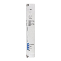
Description of the Model DLC Device Loop Card from Siemens Industry, Inc., its purpose, and system integration.

OPERATION

DLC Operational Functions

Details on how the DLC initializes, operates, maintains devices, and communicates information to the System CPU.

Controls and Indicators

Power LED Status

Description of the green POWER LED indicating power applied to the DLC card.

Card Fail LED Status

Description of the yellow CARD FAIL LED indicating a microprocessor failure.

HNET Fail LED Status

Description of the yellow HNET FAIL LED indicating communication termination.

GND Fault LED Status

Description of the yellow GND FAULT LED indicating a ground fault detection.

Alarm LED Status

Description of the red ALARM LED indicating an alarm condition detected by the DLC.

Trouble LED Status

Description of the yellow TROUBLE LED indicating a field wiring or firmware incompatibility issue.

Zone 1 Wiring Status LEDs

Indicators for Zone 1 wiring faults: Class A Open, Class A Return, and Short.

Zone 2 Wiring Status LEDs

Indicators for Zone 2 wiring faults: Class A Open, Class A Return, and Short.

PRE-INSTALLATION

HNET Network Address Configuration

Instructions for setting the three-digit HNET network address using rotary dial switches.

INSTALLATION

DLC Card Installation Procedure

Step-by-step guide for physically inserting the DLC card into the CC-5 card cage.

WIRING

Power Off and Wiring Safety

Safety warning to remove system power before installation and wiring.

External Wiring Connections

Procedure for connecting field wiring to the terminal blocks of the CC-5 card cage slot.

24VDC Power Connection Details

Instructions for connecting +24V and -24V from the PSC-12 to the DLC slot.

COMPATIBILITY

Compatible Device Identification

Lists compatible devices for UL 864 and UL 2572, including model numbers.

Loop and Device Capacity Limits

Details on loop capacity, device limits per zone, and total devices supported.

Wiring Specifications and Restrictions

Information on wire type, conduit, T-tapping rules for Class A loops, and UL/ULC listing.

Circuit Performance Parameters

Specifies power limits, wire resistance, and capacitance limits for the circuits.

Operational and Listing Compliance

Notes on multi-criteria detector programming and compliance with standards.

Cyber security disclaimer

Security Concept Importance

Emphasizes the necessity of a comprehensive, customized security concept for system operation.

Related product manuals