EasyManua.ls Logo

Siemens FDLU291 User Manual

Siemens FDLU291
6 pages
To Next Page IconTo Next Page
Page #1 background imageLoading...
Page #1 background image
008335_e_--_--
Building Technologies
2014-04-17 Control Products and Systems
Linearer Rauchmelder DLO1191
Justierset FDLU291
Inbetriebnahme
Linear smoke detector DLO1191
Adjustment tester FDLU291
Commissioning
Verwendungszweck
Der Lineare Rauchmelder detektiert den Rauch und
eignet sich für die Brandüberwachung in grossen Lager-
und Fabrikationshallen auch mit komplexen Deckenkon-
struktionen.
Er besteht aus dem eigentlichen Melder und
einem Reflektor, der dem Melder gegenüberliegend
angeordnet ist.
Intended use
The linear smoke detector detects smoke and is suited
for fire detection in large storage and factory halls, also
with complex ceiling constructions. It consists of the d
e-
tector itself and a reflector placed opposite the detector.
Der Lineare Rauchmelder fällt gemäß EN 62471 'Photo-
biologische Sicherheit von Lampen und Lampensyste-
men' in die risikofreie Gruppe (englisch: 'Exempt Group').
In accordance with EN 62471, 'Photobioligical Safety of
Lamps and Lamp Systems', the linear smoke detector falls
into the 'Exempt Group'.
Aufbau und Funktion des Justiersets
Die Inbetriebnahme erfolgt mit Hilfe eines Justiersets,
das aus einem Justiergerät, Alarmtest-Filter, Magneten,
der Zielvorrichtung, und Verbindungskabeln besteht.
Das Justiergerät erkennt automatisch den zuletzt im
Melder gespeicherten Entfernungsbereich (Range) und
das aktuelle Signal.
Die schrittweise Bedienung des Justiergerätes während
der Inbetriebnahme erfolgt über die rechte Taste unter-
halb des Displays.
Die Beleuchtung des Displays kann über die linke Taste
aktiviert werden.
Bei Nichtbenutzung schaltet sich das Justiergerät nach
5 Minuten automatisch aus.
Das Justiergerät wird mit einer 9-Volt-
Batterie betrieben,
die auf dessen Rückseite in einem Schacht unterge-
bracht ist.
Setup and function of the adjustment set
Commissioning is ensured by means of an adjustment
set consisting of an adjustment device, alarm test filter,
magnets, the sighting system and connection cables.
The adjustment device automatically detects the last
detection range stored in the detector and the current
signal.
The step-by-step operation of the adjustment device
during commissioning is ensured by the right button be-
low the display.
The display illumination can be activated by pressing the
left button.
When not used, the adjustment device will switch off
automatically after 5 minutes.
The adjustment device is operated with a 9V battery
located in a shaft at the back of the device.

Other manuals for Siemens FDLU291

Question and Answer IconNeed help?

Do you have a question about the Siemens FDLU291 and is the answer not in the manual?

Siemens FDLU291 Specifications

General IconGeneral
Power Source24 VDC
ApprovalsEN 54-7, EN 54-17
TypeSmoke Alarm
Alarm Current20 mA
Operating Temperature-20°C to +60°C
Relative Humidity≤ 95% (non-condensing)

Summary

Linear Smoke Detector DLO1191 & Adjustment Tester FDLU291: Introduction and Setup Overview

Intended Use

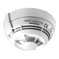
Explains the suitability of the linear smoke detector for fire detection in large storage and factory halls.

Setup and Function of the Adjustment Set

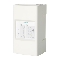
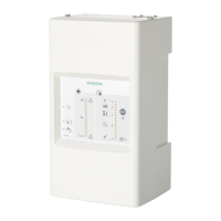
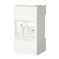
Describes the components and operation of the adjustment set used for commissioning the detector.

Detector Parameter Configuration and Installation

Parameter Setting via DIP Switches

Details how to configure detector parameters using DIP switches based on a provided table.

Detector Unit Installation

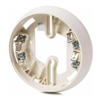
Provides instructions for physically installing the detector unit into its base, including safety warnings.

Detector Commissioning: Preliminary Optical Adjustment

Preliminary Optical Adjustment

Outlines the initial rough adjustment of the detector optics to the reflector using knurled screws.

Detector Fine Tuning with Adjustment Device

Fine Setting Procedure

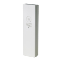
Detailed step-by-step guide for fine-tuning the detector's range and signal using the adjustment device.

Detector Initialization and Functional Testing

Detector Initialization Process

Describes the method for initializing the detector using a magnet, with a warning about measurement disturbance.

Detector Test Procedure

Explains how to perform a test alarm after initialization using a specific alarm test filter.

Optional Features and Ordering Information

Optional Detector Heating Unit Installation

Information on installing an optional detector heating unit that requires an external 24V power supply.

Product Ordering Details

Lists part numbers and descriptions for various detector models, bases, and accessories.

Related product manuals