Do you have a question about the Siemens FCI2016-U1 and is the answer not in the manual?
Provides a detailed description of the FCI2016 periphery board's purpose and capabilities.
Describes the procedure for installing the FCI2016 periphery board into the fire control panel.
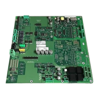
Illustrates the printed circuit board layout and identifies key components and connectors.
Explains how to configure system functions related to power supply and battery connections.
Details the wiring procedures for connecting power supplies and batteries to the board.
Covers the configuration and functionality of Notification Appliance Circuits (NACs).
Provides wiring diagrams for connecting notification devices to NAC circuits.
Details the X601 terminal block for NAC 1 class A, NAC 1-1 class B, and NAC 1-2 class B.
Explains the input for connecting to an external fire alarm control unit's NAC circuit.
Describes the auxiliary 24 V DC output for powering peripheral devices.
Information on the different types of relays and their functions.
Details the detector circuits and circuit driver 1 for managing up to 252 devices.
Illustrates wiring configurations for detector circuits using Style 6 and Style 4 methods.
Explains the meaning of LED indicators on the FDnet/C-NET detector circuit.
Describes the function of the S100 RESET button on the periphery board.
Provides detailed technical specifications and parameters for the periphery board.
Provides a detailed description of the FCI2017 periphery board's purpose and capabilities.
Describes the procedure for installing the FCI2017 periphery board into the fire control panel.
Illustrates the printed circuit board layout and identifies key components and connectors.
Explains how to configure system functions related to power supply and battery connections.
Details the wiring procedures for connecting power supplies and batteries to the board.
Covers the configuration and functionality of Notification Appliance Circuits (NACs).
Provides wiring diagrams for connecting notification devices to NAC circuits.
Details the X601 terminal block for NAC 1 class A, NAC 1-1 class B, and NAC 1-2 class B.
Explains the input for connecting to an external fire alarm control unit's NAC circuit.
Describes the auxiliary 24 V DC output for powering peripheral devices.
Information on the different types of relays and their functions.
Details the detector circuits and circuit drivers for managing devices.
Illustrates wiring configurations for detector circuits using Style 6 and Style 4 methods.
Explains the meaning of LED indicators on the FDnet/C-NET detector circuits.
Describes the function of the S100 RESET button on the periphery board.
Provides detailed technical specifications and parameters for the periphery board.
| Brand | Siemens |
|---|---|
| Model | FCI2016-U1 |
| Category | Smoke Alarm |
| Language | English |