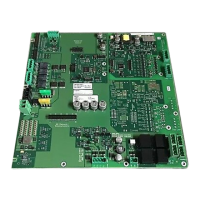
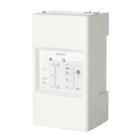
Periphery board (500p) FCI2017
Detector circuits, circuit driver 1 (circuits 1 and 2) and circuit driver 2 (circuits 3 and 4)
2
38 | 46
2.8.1 Wiring
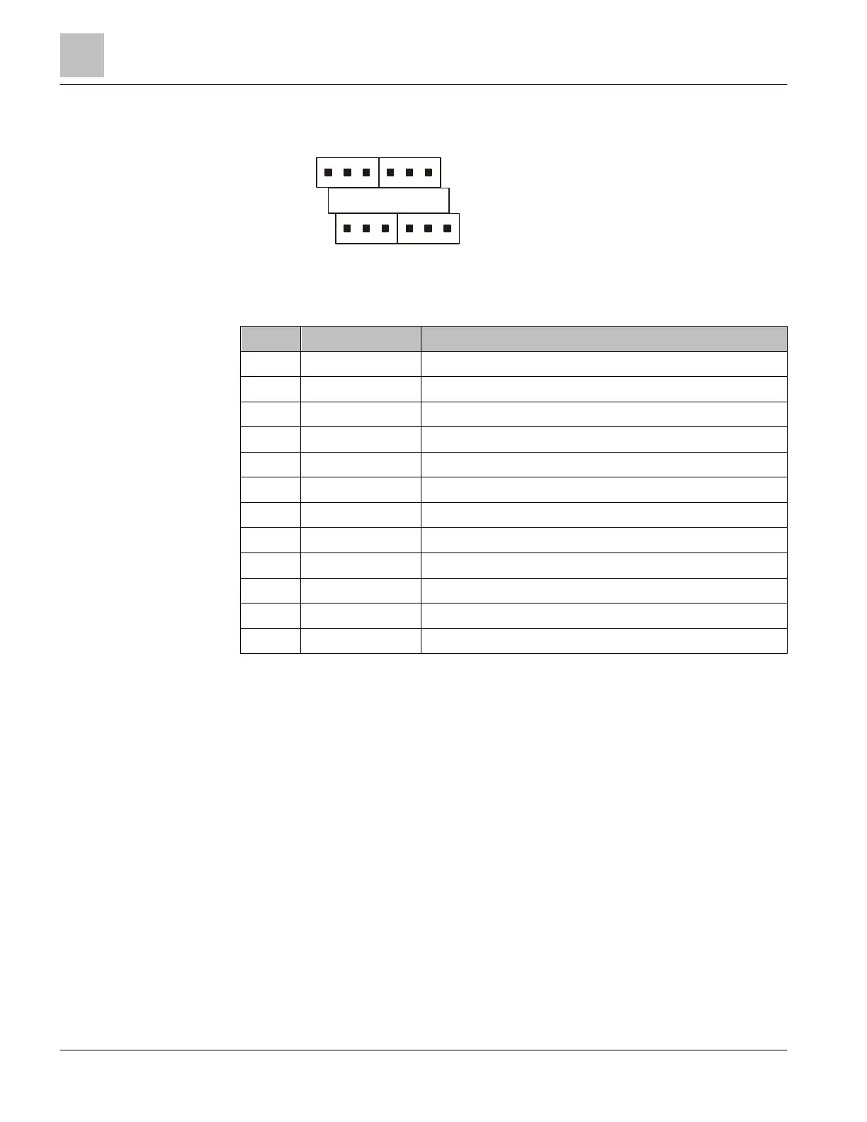
2.8.2 X1101 Relay terminal block
Pin Designation Description
1 C Common contact common alarm relay
2 NC Normally closed contact common alarm relay
3 NO Normally open contact common alarm relay
4 C Common contact common trouble relay
5 NC Normally closed contact common trouble relay
6 NO Normally open contact common trouble relay
7 C Common contact common supervisory relay
8 NC Normally closed contact common supervisory relay
9 NO Normally open contact common supervisory relay
10 C Common contact programmable relay
11 NC Normally closed contact programmable relay
12 NO Normally open contact programmable relay
Admissible cable cross-section: 1 x 12…18 AWG or 2 x 16…18 AWG
NO/NC (normally open / normally closed) relates to the fire detection system's normal
status.
2.9 Detector circuits, circuit driver 1 (circuits 1 and 2) and
circuit driver 2 (circuits 3 and 4)
The periphery board (500p) has two independent integrated circuit cards. Each
integrated card is a driver that has 2 circuits that can handle a maximum of 252
devices. Circuit driver 1 supports circuits 1 and 2 and circuit driver 2 supports circuits 3
and 4.
Each circuit driver can be configured for two style 6 circuits or four style 4 circuits:
The detector circuits are isolated from the periphery board's main circuit. Each circuit
card has a microprocessor which supervises ground fault, short-circuit, open circuit,
and line capacity.
1
6
7
12
C NCNO
TroubleAlarm
User
Supervisory
NCNO
C NC NO C NC NO