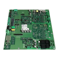
Periphery board (250p) FCI2016
1
20 | 46
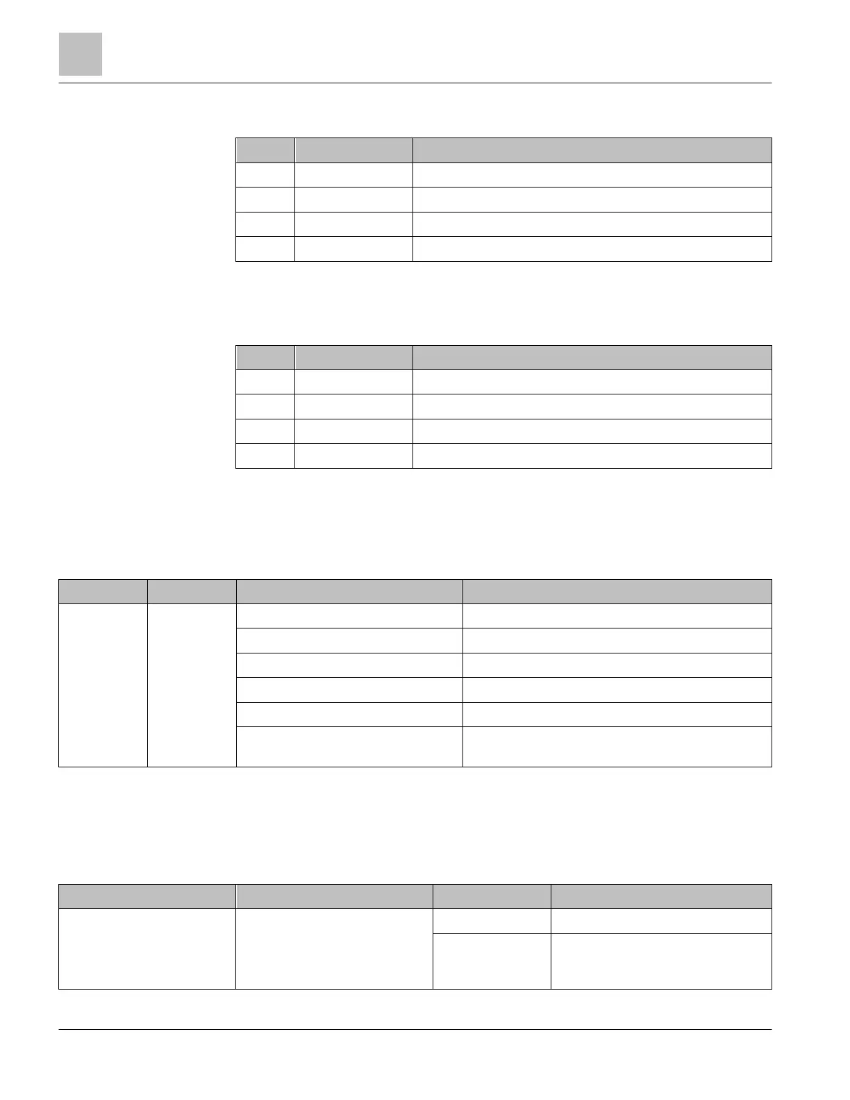
1.9.2 X1401 terminal block – detector circuit 1
Pin Designation Description
1 2- Return feed for circuit 1-2
2 2+ Positive feed for circuit 1-2
3 1- Return feed for circuit 1-1
4 1+ Positive feed for circuit 1-1
Admissible cable cross-section: 1 x 12…18 AWG or 2 x 16…18 AWG
1.9.3 X1402 terminal block – detector circuit 2
Pin Designation Description
1 2- Return feed for circuit 2-2
2 2+ Positive feed for circuit 2-2
3 1- Return feed for circuit 2-1
4 1+ Positive feed for circuit 2-1
Admissible cable cross-section: 1 x 12…18 AWG or 2 x 16…18 AWG
1.10 Indicators
LED indicators on the FDnet/C-NET detector circuit
LED Color Condition Meaning
H1301 Yellow OFF Normal condition
ON Startup problems on integrated circuit card 1
1 x flash per second Fail-safe active (no communication to the PMI)
2 x flash per second Fail-safe active and local alarm
1 x flash every 2 seconds Fail-safe active and signalization (local alarm)
1 x flash per second and 2 x rapid
flash every 2 seconds
Fail-safe active and local alarm and signalization
1.11 Reset Buttons
1.11.1 S100 RESET periphery board
Button Function Position Meaning
S100
Reset main microprocessor on
periphery board
Not pressed Normal
Pressed
Resets only the main
microprocessor on the periphery
board.